Summary of RC Arduino Domino Layer With Bluetooth App Control
This article details the construction of a programmable, remote-controlled automatic domino laying machine. Using an Arduino Uno, DC motors, and 3D-printed parts, the device can lay rows of dominoes while moving forward, backward, or around corners. It supports control via Arduino IDE instructions or a Blynk app over Bluetooth. The build involves assembling two main body halves, installing limit switches for positioning, and integrating a motor-driven ejector mechanism to place dominoes automatically.
Parts used in the Automatic Domino Laying Machine:
- Elegoo Arduino Uno
- Micro continuous rotation servo
- Micro 180º servo
- LM317 DC-DC Converter
- Six AA Battery Holder
- AA Batteries
- 1:90 TT DC Motor
- L298N Motor Driver
- Limit Switch with roller arm
- 1602 LCD Shield with keypad
- HM10 Bluetooth Module
- M3 and M5 Bolts (various lengths)
- Rubber Bands
- Dominos
- 4 Way Wire Connector
- Electrical Hookup wire
- Velcro Cable Tidy
- Filament for 3D printing (Silky silver PLA and White PLA)
- Hot melt glue
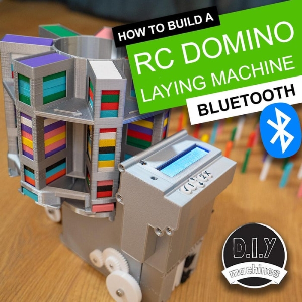
How to 3D print and assemble your very own programmable and remote controllable automatic domino laying machine.
Who likes knocking down absurdly long runs of dominoes? I do. Who doesn’t like laying them all by hand. I don’t. That’s why I made this. ?
Using some basic electronics this machine can line up well spaced rows of wooden dominoes. You can drive it around corners, forwards and backwards – just don’t drive into your already laid dominoes. You can enter a list of instructions to your robot via the Arduino IDE, upload with USB and then send it on it’s way to follow your instructions, or you can open the Blynk phone app and drive it live via bluetooth.
Step 1: Video Instructions
If you would like see the machine in action or prefer to follow a video guide then I have made two videos to go with these instructions. The first one covers the majority of the 3D printing, assembly, electronics, and programming from the Arduino IDE.
The second video show how to upgrade the machine with the addition of bluetooth so that we can drive it around like an RC car (laying dominoes at the same time of course) using a free app built in Blynk.
Step 2: Bill of Materials and Other Resources
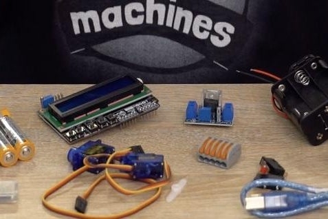
You’re going to need some supplies to build one of your own. Here is a list of those items with links to them on Amazon:
- Elegoo Arduino Uno (x1) – https://geni.us/ArduinoUno
- Micro continuous rotation servo (x1) – https://geni.us/360MicroServo
- Micro 180º servo (x1) – https://geni.us/MicroServo
- LM317 DC-DC Converter (x1) – https://geni.us/LM317
- Six AA Battery Holder (x1) – https://geni.us/6AABatteryHolder
- AA Batteries (x6) – https://geni.us/AABatteries
- 1:90 TT DC Motor (x1) – https://geni.us/1-90GearedTTMotor
- L298N Motor Driver (x1) – https://geni.us/L298N
- Limit Switch with roller arm (x2) – https://geni.us/ContactSwitch
- 1602 LCD Shield with keypad (x1) – https://geni.us/1602LCDKeypad
- HM10 Bluetooth Module (x1) – https://geni.us/HM10Bluetooth
- M3 and M5 Bolts – https://geni.us/NutsAndBolts M3x6 (x2) M3x10 (x21) M5x15 (x2) M5x20 (x2) M5x25 (x1)
- Rubber Bands – https://geni.us/RubberBands
- Dominoes I used (x lots) – https://geni.us/Dominoes
- 4 Way Wire Connector (x1) – https://geni.us/WagoConnectors
- Electrical ‘Hookup’ wire – https://geni.us/22AWGWire
- Velcro Cable Tidy (for domino ejector) – https://geni.us/VelcroCableTidy
- Filament for 3D printing:- Silky silver from Geeetech: https://geni.us/GeeetechSilkSilverPLA
– White PLA: https://geni.us/GeeetechSilkSilverPLAI have also included a wiring diagram here as some people prefer to be able to refer to one whilst following the instructions.I will attach the 3D CAD files for each part at the appropriate point in the instructions. You can also find them all in one place on Thingiverse: https://www.thingiverse.com/thing:4694940
Step 3: 1st Half of the Body and Servo
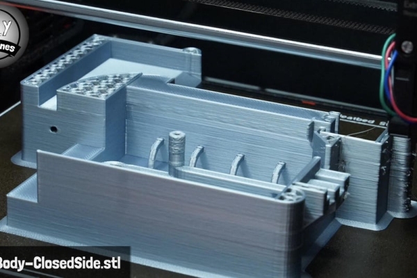
We need to start with the first half of the body which is a 3D printed part. I have printed all my parts for this project in PLA plastic – PETG would also be fine.
The first part is called ‘MainBody-ClosedSide.stl. I printed mine at a layer height of 0.3mm (as I had a larger 0.6mm nozzle fitted to my printer at the time of printing this) and added a brim to ensure adhesion. There is no needs for support on this part – I’ve worked hard to avoid them where possible in the design.
Once printed we can take the continuous rotation servo and cut off the end of the connector. Use some hot melt glue to then secure it in its recess towards the top right of the print. The wires should exit to the left through the little passage way.
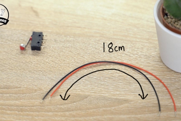
Step 4: The 1st Contact Switch
For this step will you need:
- Contact switch x1
- Some wires
- Hot melt glue
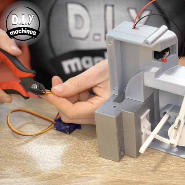
Prepare two 18cm long lengths of wire. Solder one each to the common and normally open legs on the contact switch. On mine these are marked as C and NO.
The wires can then be threaded though the tunnel in the 3D printed part. You can then use some hot melt glue to attach the contact switch in position. Its back edge should push up against the ridge shown by the arrow I added in the photos.
Use hot melt or some other reworkable glue as you may need to adjust its position later. Also be sure to keep the glue from interfering with the switch mechanism itself.
Step 5: Installing DC Geared Motor
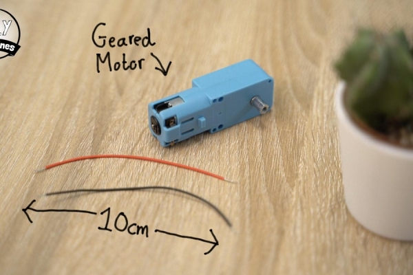
For this step will you need:
- DC Geared Motor (at lest 1:90 gearing)
- Wires
Cut, strip, and tin a pair of 10cm lengths of wire which can then be soldered to the two terminals on the DC motor.
Ensure the wires are exiting away towards the back of the motor and apply some hot melt glue to act as strain relief to both the wires and the small little tabs which they have just been soldered to.
Use some more glue to fit the DC motor into the housing whilst ensuring that the shaft of the motor is central in its hole when seen from the other side of the housing.
Step 6: Add DC Motor Gears & Axle
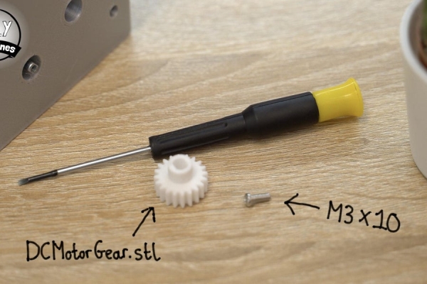
For this step will you need:
- Printed parts:
- DCMotorGear.stl
- DoubleCog.stl
- DriveAxle.stl
- PoweredWheel.stl
- M3 x 10mm bolt (x2)
- M5 x 25mm bolt (x1)
The next 3D printed part required is the ‘DCMotorGear.stl. Again, no support are needed for this part. Use the first M3 x 10mm bolt to fit this to the shaft of the DC motor from the outside.
If your shaft doesn’t have a threaded insert then it can also be fitted with glue.
Now the ‘DoubleCog.stl’ and ‘DriveAxle.stl’ parts can be printed and joined together with the other M3x10 bolt. This sub assembly is then passed through the adjacent hole in the printed body so that the large teeth of the gear mesh with the already installed gear.
To complete this set of cogs pass the M5x25mm bolt through the printed ‘PoweredWheel.stl’ and then attach this to the main body so that the smallest of the cylinders on the print is against the main body and the largest smooth cylinder of the print is on the outside. Once the bolt has been tightened, loosen it off slightly so that the wheel can rotate freely but does not wobble too much.
Step 7: Attach Back of the Main Body
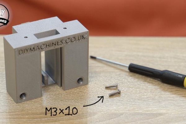
For this step will you need:
- Printed parts:
- MainBody-Back.stl
- M3 x 10mm bolt (x2)
I recommend printing this part on its back so that the writing is facing upwards. this help to ensure that the the thin fins are printed well and that no bridging occurs where we need dominoes to be able to easily slide past.
After you have printed the MainBody-Back.stl and removed the supports we can attach it to the main body with the two M3x10mm bolts.
One through the access hole in the front and the other from below. (Through the square opening).
Step 8: Prepare Domino Ejector
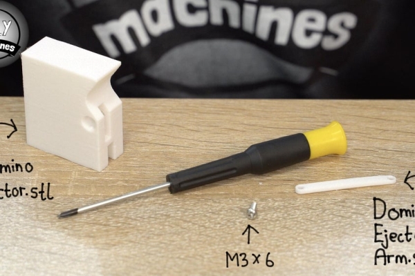
For this step will you need:
- Printed parts:
- DominoEjector.stl
- DominoEjectorArm.stl
- M3 x 6mm bolt (x1)
Print the ‘DominoEjector.stl’ and ‘DominoEjectorArm.stl’. When printing the DominoEjector part it is important to print it upside down. This results in the layer lines running in the same direction that it will slide back and fourth through the machine – reducing friction and noise. Why upside down? This also is how this part has been designed so that we can print it without supports which will also help to ensure a smooth motion.
The arm is inserted into the cutout and secured with the M3 x 6mm bolt through the side of the printed part.
This assembly can then be slid into place by inserting the end with the arm protruding through the back of the domino machine first followed by the larger ejector itself.
Step 9: Connect Arms to the DC Motor
For this step will you need:
- Printed parts:
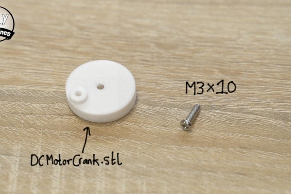
- DCMotorCrank.stl
- DominoCollectorArm.stl
- M3 x 10mm bolt (x3)
The 3D printable ‘DCMotorCrank.stl’ is fitted over the shaft of our DC motor on the inside of the main housing. Again, if your shaft is threaded like mine you can use a bolt to secure the printed part. If their is no thread on your shaft you can use glue instead.
The DominoCollectorArm.stl component is then installed, first by passing an M3 x 10 bolt though the long slot in the arm. Ensure that the hooked end of the arm is facing towards the back of the machine (away from the servo) when you install it – check the photos if you are not sure what I mean.
This should not be tightened so much as to restrict the movement of the arm. It should allow the arm to slide up and down freely.
The final M3x10 bolt is used to connect the two arms to the crank. This needs to be done with the domino collector arm (the large one with a slot in it) first so that it touches the crank, followed by the thinner domino ejector arm on top of this. This bolt also should be left slightly loose so that both arms can freely rotate around the shaft of the bolt without too much wobble.
Step 10: Starting ‘the Other Half’
For this step will you need:
- Printed parts:
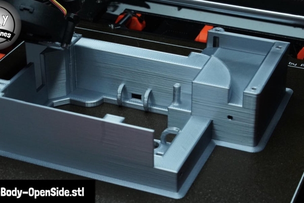
- ‘MainBody-OpenSide.stl’
- Wire connector
‘MainBody-OpenSide.stl’ is the next part that can be 3D printed. This piece does not require any supports and mine was printed in PLA like the rest of the project.
If you are using a Wago connector as I am, now is a good time to open the little sprung arms for easier connection of the wires later. Use some glue to fix it to the underside of the printed housing .
Step 11: The Second Contact Switch
For this step will you need:
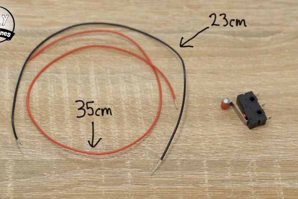
- Contact switch
- Wires
Measure, strip, and tin a couple of wires. One should be 23cm long and the other 35cm long. These can then be soldered to the same common and normally open legs like we did with our first switch. It does not matter which length wire is connected to which leg.
Use some glue to fix it to its platform at the bottom of the print. Ensure that the orientation (the way its arm is sprung) matches the switch in the photos for this step and that the switch is positioned so that it right side is against the right stop and the back is against the back stop.
The hoops on this print are for threading our wires through. Thread both the wires for the contact switch through the first two hoops. Thread the 35cm long wire though the runner just behind the printed column so that it comes out at the top of the print. Use some masking tape to label this wire as A3 as this is the pin we will be connecting it to on our Arduino later.
The 23cm wire is instead passed around the column and carries on through the row of hoops at the top before being inserted into our wire connector.
Step 12: DC Motor Driver (L298N)
For this step will you need:
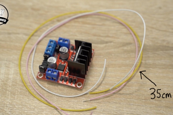
- L298N
- Wires
There may or may not be some jumpers fitted onto the pins on your motor driver. You need to ensure that there is one fitted over the two pins behind the terminal blocks (see the photo). This connects the 5v terminal to the boards linear regulator and will provide 5v to power our Arduino and LCD shield.
If there are any additional jumpers blocking your access to a pin they can be removed.
Prepare three lengths of 35cm long wire. These need to be connected to the pins marked as ENA, IN1 and IN2. I soldered mine. All three of these wires should then be threaded through the first two hoops and then through the tunnel towards where our Arduino will be later. Label each of these wires.
Connect a 22cm length of wire to the both the VCC and ground terminals. A new 30cm length of wire (yellow in the images) is connected to the terminal marked as 5v.
Thread the 22cm VCC wire though the first two hoops and then into the as yet unused hole below the pin/column for connection to our battery later. The ground wire goes all the way around through all the hoops and is connected to our wire connector.
The 5V wire goes through the first two hoops and then through the tunnel to join where our other wires are waiting to be connected to the Arduino later. Don’t forget to add a label to the wire.
Finally we can use some glue to fit the motor driver board itself into place. There is a ledge at the back of the print which the board should be butted up to, as well as the ledge on the side of the print.
Gently pull on our labelled wires to pull through any slack inside the housing without putting to much strain on the wires.
Step 13: Installing 180° Servo
For this step will you need:
- 180° servo
As we did with the first servo, trim the connector off the end of its wire. Peel the orange signal wire all the way back to separate it from the other two wires on both the servos (the one we just trimmed as well as the one already installed in the first half of the housing we worked on).
Trim the length of the brown and red power wires on both servos to around 9cm in length.
Pass all three wires for the 180°steering servo through the hole in the front of the main body and then use some glue to set the servo in place.
Source: RC Arduino Domino Layer With Bluetooth App Control
- How do I control the machine?
You can enter a list of instructions via the Arduino IDE to upload via USB, or use the Blynk phone app to drive it live via Bluetooth. - What material should I use for 3D printing the parts?
The author printed all parts in PLA plastic, though PETG would also be fine. - Can I drive the machine around corners?
Yes, you can drive the machine around corners, forwards, and backwards, but you must avoid driving into already laid dominoes. - How do I prepare the DominoEjector part for printing?
You should print the DominoEjector part upside down so layer lines run in the direction of sliding motion to reduce friction and noise. - Does the second contact switch require specific wire labeling?
Yes, the 35cm long wire from the second switch should be labeled as A3 because it connects to that specific pin on the Arduino later. - How is the L298N motor driver powered?
A jumper must be fitted over the two pins behind the terminal blocks to connect the 5v terminal to the board's linear regulator for powering the Arduino. - What type of servos are used in this project?
The project uses one micro continuous rotation servo and one micro 180º servo. - Where can I find the 3D CAD files for the parts?
The files are attached at appropriate points in the instructions and can also be found together on Thingiverse.