Introduction
In the previous tutorial I showed how to build a weather station using DHT11 and BMP180 with an Arduino. However, the project has a downside which is the power consumption of the 16X2 LCD. If we were building a battery powered project with the desire to last for several weeks and probably several months, like a weather station for instance, then we’ll have to replace the LCD keypad shield from the previous tutorials and go for something like the low powered Nokia 5110 84×84 LCD display. In this tutorial I will be showing you how to drive this display with the Arduino and thus build projects with longer battery life.
Project parts
Since we are just going to drive the display we won’t be needing sensors for this tutorial, however we will need the components listed below which include the Nokia 5110 itself and we will show how to drive the display using an Arduino board.
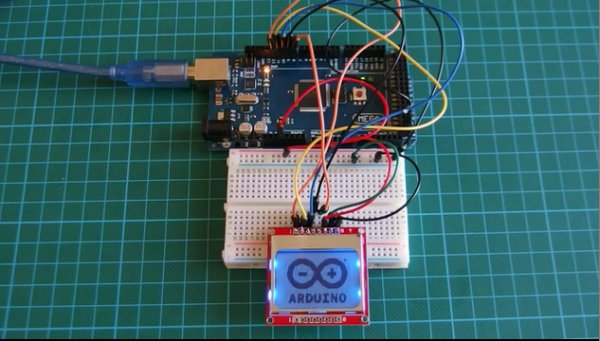
1. Nokia 5110 84×84 LCD
2. Arduino Mega
3. Jumpers
4. Breadboard
5. Power bank
The Nokia 5110 display is basically a graphic LCD display useful for a lot of applications. It was intended originally to be used as a screen for cell phones and was used in lots of mobile phones during the 90’s. This display uses a low powered CMOS LCD controller/driver PCD8544, which drives the graphic display of size 84×48. It is very cheap and costs about 3$. You can get one here.
The Nokia 5110 LCD can display text, graphics as well as bitmaps. When this display is fully lit, it draws about 10mA but with the backlight off, it draws as low as 0.4mA. The power consumed by this display is very low compared to that of the keypad LCD shield used in the previous tutorial. I will be using the Arduino Mega for this tutorial as usual and you can buy one here. You can also buy jumpers, breadboards and power bank which you will be needing for this tutorial.
With the components acquired (links attached to the list), lets wire them up.
Schematic
The display has two sides to which headers pins can be connected. You can pick one of the sides and solder header pins so that the display can fit firmly on the breadboard. The display works best when powered with 3.3 volts.
The light pin, when connected to ground turns the backlight “ON” while connecting it to VCC turns it “OFF”.
Read more: How to drive Nokia 5110 84×48 LCD display with Arduino