Even after 25 years of its introduction to consumer market, infrared communication is still very relevant in recent days. Whether it is your 55 inch 4K television or your car sound system, everything needs an IR remote controller to response to our commands. There are many technologies available in the industry, say Bluetooth, RF or even WI-Fi, but we have stuck to infrared communication for so long, that has some very valid reasons behind it. First of all they are very cheapest solution, they costs literally cents, apart from that they are reliable and most importantly the ease to use. Also don’t overlook the low power consumption of this circuit compared to RF or Bluetooth remote. So in today’s video let’s make a project by which we can control our home appliances using these IR remotes. Also I will be implementing a timer function to switch on/off devices without our direct involvement. Starting with block diagram, coding, circuit diagram to final PCB designing, I will guiding you through the whole process in detail.
Before starting, just a small reminder. Please do subscribe to our channel if you like this tutorial.
Channel link – www.youtube.com/c/being_engineers1
We have also made a detailed video about the same topic. So if you don’t feel like reading all through then watch the video to get more insights. I am attaching the link below.
That’s it. Now let’s start building this project.
Step 1: Gather All the Required Components
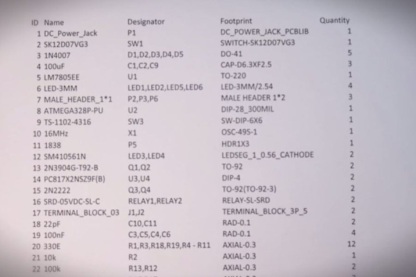
First of all gather all the required components according to the given BOM.
- DC female adapter X 1
- Slide switch X 1
- Male headers
- 1N4007 diodes X 5
- 100uF caps X 3
- 100nF caps X 4
- 7805 voltage regulators and heat sink X 1
- 3mm red led X 2
- 3mm green led X 2
- 28 pin IC base X 1
- Atmega328P-Pu X 1
- 16.00 MHz crystal oscillator
- 22pF caps X 2
- 330E resistors X 12
- 1K resistors X 2
- 10K resistor X 1
- 100K resistors X 2
- 470E resistors X 2
- 2N3904 transistor X 2
- 2N2222A transistor X 2
- 1838 IR receiver X 1
- PC817 X 2
- 5v SPST relay X 2
- 3 pin terminal block X 2
These are the main components that you need to make this project. But with these you also need basic soldering equipments, hardware accessories, breadboard and an arduino
I will not use a general arduino board in this project. Rather I will use a DIY one. The coding will be done using arduino IDE, and everything will be same like any other arduino project. But just at the last moment I will remove the pre-programmed IC and will place it in my PCB.
You can watch this video of mine about how to make DIY arduino UNO at home –
Once you have all these items, it’s time to draw the circuit.
Step 2: Design the Working Circuit
I used the online platform named Easyeda to design the circuit.
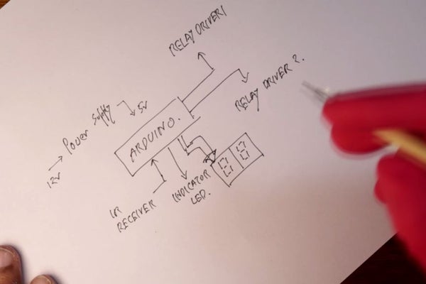
The circuit will have mainly this blocks –
- Power supply module – converts 9-12V DC input to 5V DC to power the circuit.
- Microcontroller – I will use a ATmega328P IC as the microcontroller. It’s the same one which can be found on any arduino UNO, nano or pro mini.
- IR receiver – I will use a TP1838 IR receiver module that will be connected to the microcontroller.
- Timer indicator – A 3mm red led will denote the status of the timer.
- Seven segment display – 2X7 segment CA display will show visual information via alphanumeric character.
- Relay Driver – Two relays will be interfaced with the microcontroller via appropriate relay driver circuit.
The circuit that worked for me is this – https://bit.ly/2EvVjee
Watch this video to know how to make relay driver board for arduino –
Step 3: Design the PCB and Order It
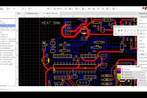
Once the circuit design is completed, It’s time to make the PCB. I used the JLCPCB website to make my prototype board. They are one of the best in PCB making in recent days I guess.
After circuit design is complete, convert the circuit to PCB and design the PCB in Easyeda website. Be patient with it. A mistake here will ruin your PCBs. Check multiple time before generating gerber file. You can also check the 3d model of your PCB from here. Click on make gerber file and from there you can directly order this board via JLCPCB. Upload the gerber files, select proper specification, don’t change anything is this section. Keep it as it is. This are good enough settings to start with. Place the order. You should get it in a week.
PCB PDF in 1:1 Scale – https://bit.ly/2Enl2oh
PCB Gerber File – https://bit.ly/2zXT0g1
Step 4: Get the HEX Values of Your IR Remote
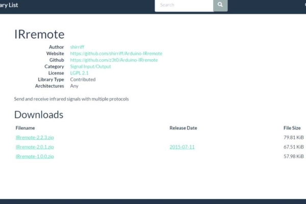
In this step you need to know the Hex values that your remote transmits to arduino. We will use this code later on in the final code. For this you will need the IRRemote library for arduino.
IRRemote Library – https://bit.ly/2EmZeZB
you can download the library and install it in the IDE. Open the IrrecvDemo example sketch and upload the code to the arduino. Open serial monitor and start pressing remote buttons one at a time. You will see corresponding Hex code in the serial monitor. I have copied all the codes in a word file for future references. Also you can just note down the hex codes of those buttons that you are intending to use in this project. After that it’s time to construct the main program.
Step 5: Write the Program and Upload It to the Arduino
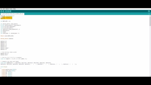
This is the final code that has to uploaded in the arduino – https://bit.ly/2LfQ2YA
One thing you need to understand you need some basic knowledge of arduino timer, interrupt and other advance concepts to understand the code properly. We don’t normally use timers and interrupts in arduino just because it increases the complexity of a code. But this project demanded the usage of interrupt and timer.
Also you need two more libraries two compile the code properly –
- Timerone – https://bit.ly/2PE0ABe
- Pinchangeinterrupt – https://bit.ly/2ULS9aM
Compile and upload the code to arduino. Once done, remove the IC from the arduino. We will place it in the PCB.
Source: How to Control Home Appliances With TV Remote With Timer Function