Summary of How to Build Your Own DigiDice | Electronic LED Dice
This article guides users through constructing a custom digital dice using an Arduino Nano, 7 LEDs, and a 3D-printed enclosure. The project involves designing two custom circuit boards on proto board for the LEDs and a pushbutton, assembling them with various screws and resistors, and programming the Arduino to generate random numbers with color animations upon button press.
Parts used in the DigiDice:
- Arduino Nano
- Pushbutton
- 7x 5mm LEDs
- Resistors (7x 220 Ohm; 1x 10 kOhm)
- Self-tapping screws (5x M3x8mm; 3x M3x5mm)
- Machine screws (6x M2x6mm)
- 9V Battery & battery snap
- Small slide switch (20mm center-to-center mounting holes)
- 3D Printer filament (PLA)
- Strip grid proto board
Here is an Instructable on how to build a digital dice that uses LEDs as well as an Arduino Nano to generate random numbers and display them in vibrant colours. The housing is fully 3D printed and some circuits have to be custom made. To use the dice, a button is simply pressed and after a quick animation a number will be displayed.
Supplies
Tools:
>3D Printer
> Soldering iron and solder wire
> Screw drivers
> Wire stripper and side cutter
> Scroll saw (Or anything that can cut proto board)
> Rotary tool with cutting disc (Optional)
Off-the-shelf parts:
> 1x Arduino Nano
> 1x Pushbutton
> 7x 5mm LEDs (Choose your favourite colour!)
> Resistors: 7x 220 Ohm; 1x 10 kOhm
> Self-tapping screws: 5x M3x8mm; 3x M3x5mm (Alternatively, use 8x longer M3 screws and cut them to length)
> Machine screws: 6x M2x6mm
> 9V Battery & battery snap
> Small slide switch, mounting holes 20mm center-to-center
Other materials:
> 3D Printer filament (PLA works just fine)
> Strip grid proto board (We will use this to make custom circuits)
Step 1: 3D Printed Parts
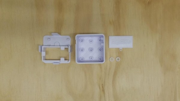
First you need to 3D print the enclosure wich will house all the other parts. The STL files are attached to this step. The only part that needs support material is the base.
Step 2: Main Circuit Layout
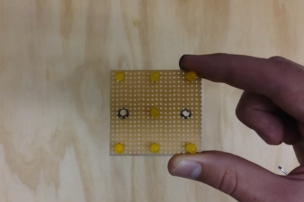
Now we will create a custom circuit board to seat the LEDs in the right positions, and distribute power among them.
Cut a piece of proto board that has 20 holes in width and 19 holes in height. Drill 3.5mm mounting holes along the center row of solder holes, spaced 36mm apart center-to-center (See picture). Solder the LEDs in the positions as shown in the image. These positions need to be exact as the LEDs need to line up with the holes in the 3D printed enclosure.
Step 3: Main Circuit Assembly
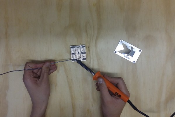
Now build the circuit shown in the schematic above by adding a 220 Ohm resistor to each LED’s positive (anode) as well as some wires to connect to the Arduino. The loose ends in the schematic represent wires that connect to the Arduino according to their individual labels. It doesn’t matter too much how you place all the components, as long as you end up with a circuit that is representative of the diagram. The photo shows a quick and dirty job I did that worked perfectly.
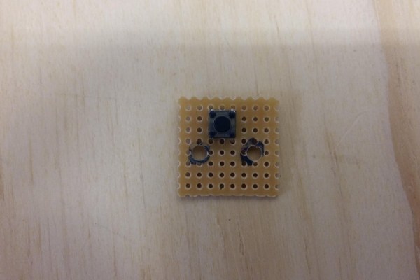
Using the same process as before, we need to make a smaller circuit to seat the pushbutton. This circuit will be built on a piece of proto board with an 8×8 hole footprint. Refer to the pictures for the placement of the button and holes as well as the circuit diagram. A 10 kOhm resistor is being used to pull the button’s default output to LOW (0 or OFF) by deviding to ground. 3.5mm Mounting holes should also be drilled here, spaced 12mm apart center-to-center.
Step 5: Remove the ICSP Pins on the Arduino
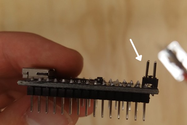
For this step you simply need to desolder the ICSP pins on the Arduino or else it won’t fin in the enclosure.
Step 6: Initial Assembly
Next, mount the Arduino Nano to the base using 4x M2 screws. Also mount the two circuits we made to the shell with M3 x 8mm screws using the plastic washers to prevent the screws from shorting out the circuit. The pushbutton circuit has 2 standoffs that it can mount to and the button should align to the cutout button in the shell. You can test it by pressing the button on the shell and listening for a click sound to hear if the button is beign actuated.
Solder one lead from the battery snap to the slide switch so the dice can be toggled on and off later.
Step 7: Final Assembly
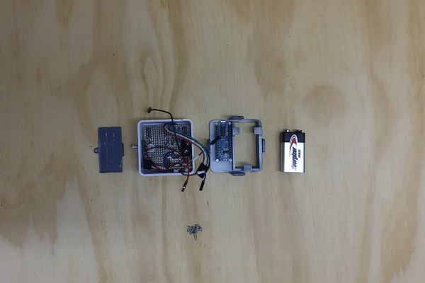
Now we will put it all together. For this step, you will need all the components you’ve made so far, in addition to the 9V battery and the remaining screws.
Install the slide switch into the casing, securing it with two M2 screws with the wires poking through the hole.
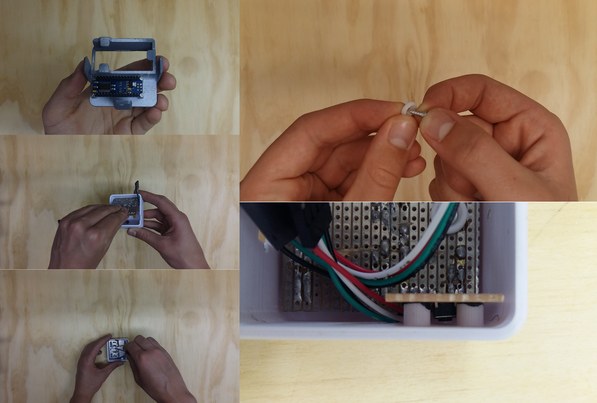
Connect all the wires from the two custom circuit boards to their respective pins on the Arduino (refer to the diagrams from steps 3 & 4) , as well as the power connectors from the battery and switch which has to connect to VIN (positive) and GND (negative) on the Arduino. Bring the base and shell together so that the gap on one side of the shell aligns with the USB port on the Arduino. Shove all the wires in until the two parts sit flush agaist each other. Note that the battery snap has to be loosely placed in the battery compartment so that the battery can be easily connected.
Fasten the two parts together using three M3x8mm screws as shown in the photo.
Now simply connect the battery to the snap and slide it into the compartment. Close it off using the battery cover and an M3x5mm screw.
And that’s it! Your DigiDice is now fully assembled and ready for some code.
Step 8: Upload the Arduino Code
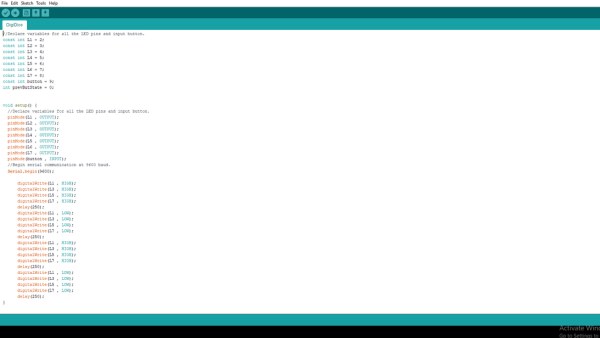
The final step is to upload the Arduino code attached to this step. You will need to install the Arduino IDE (unless you already have it installed, of course). It can be downloaded here. Connect the USB port on the arduino to your computer. You will notice a cutout in the casing where you can directly plug into the Arduino. Next open the code and select the correct port and board in the toolbar. Once you did that, click the upload button in the top left corner of the screen and the code should upload.
You can now unplug the dice, toggle it on and press the button. It should display a short rolling animation and then a random number. Enjoy!
Source: How to Build Your Own DigiDice | Electronic LED Dice
- How do I create the custom circuits for the LEDs?
Cut a piece of proto board with 20 holes in width and 19 holes in height, drill 3.5mm mounting holes spaced 36mm apart, and solder the LEDs in exact positions. - What is the purpose of the 10 kOhm resistor in the pushbutton circuit?
The 10 kOhm resistor pulls the button's default output to LOW by dividing to ground. - Why must the ICSP pins be removed from the Arduino?
The ICSP pins must be desoldered because they prevent the Arduino from fitting inside the enclosure. - How should the plastic washers be used during assembly?
Plastic washers are used with M3 x 8mm screws to prevent the screws from shorting out the custom circuits when mounting them to the shell. - Where do the power connectors from the battery and switch connect on the Arduino?
The positive wire connects to VIN and the negative wire connects to GND on the Arduino. - Can I use any type of filament for the 3D printed parts?
Yes, PLA works just fine for the 3D printed enclosure. - How do I access the USB port after final assembly?
The casing has a specific cutout designed to align with the gap on one side of the shell, allowing direct access to the Arduino USB port. - What happens when the button is pressed after uploading the code?
Pressing the button triggers a short rolling animation followed by the display of a random number.