This Zoom emergency quit button lets you exit out of your meeting in an instant. It is simple to make and requires very little electronics experience. I built this because I was always searching around for the quit button on the bottom of the screen and seemed to always be that last person to leave every meeting. Now that I have built this emergency quit button I can exit any Zoom meeting like a champ. I would say that my quality of life has now improved 357% (give or take).
Supplies
(X1) Emergency Button Assembly
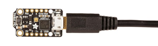
(X1) Adafruit Trinket M0
(X1) Micro USB Cable
(X2) 22AWG M4 Fork Spade Terminal Connectors
(X2) 6″ Stranded Wires
(X1) Momentary pushbutton (optional)
Tools:
(X1) Soldering Iron Kit
(X1) Wire Stripper
(X1) Screwdriver
(X1) Box Cutter
Note: Some of the links on this page are affiliate links. This does not change the cost of the item to you, but I do make a small commission if you click on the link and purchase something. I use the money that I make from this to create more projects. Should you want me to recommend an alternate supplier, let me know.
Step 1: Setup the Software
This project assumes that you have some working knowledge of Arduino. Nevertheless, I will gloss over the software setup process here.
First and foremost, download the Arduino IDE if you have not done so already.
Next, you will need to add the Adafruit Trinket M0 to the Arduino IDE. The easiest way to do this is to follow the install instructions on the Adafruit page.
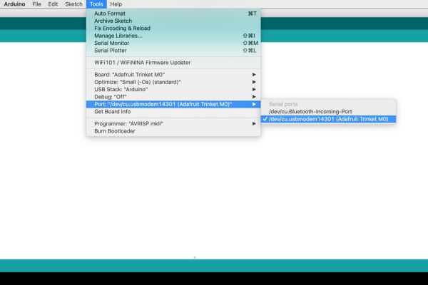
Finally, configure the board as follows
Tools > Board > Adafruit Trinket M0
Tools > Port > /dev/cu.usbmodem (or similar)
Step 2: Program the Board
Upload the following code to the board:
// ******************************************************
//
//            Code for quitting Zoom quickly
//
//           Designed for Adafruit Trinket M0
//                   by Randy Sarafan
//
//               For more info check out:
//  https://www.instructables.com/Easy-Zoom-Quit-Button/
//
// ******************************************************

// Add the keyboard library
#include <Keyboard.h>

void setup() {

    // Configure Pin 2 as input switch.
    // Triggered when connected to ground.
    pinMode(2, INPUT_PULLUP);

    // Start running the board as a virtual computer keyboard
    Keyboard.begin();

}

void loop() {

    // Check for a button press event
    if (digitalRead(2) == LOW) {

        // Press command w and wait 1/10 second
        Keyboard.press(KEY_LEFT_GUI);
        Keyboard.press('w');
        delay(100);

        // Release all keyboard keys
        Keyboard.releaseAll();

        // Press the return key and wait 1/10 second
        Keyboard.press(KEY_RETURN);
        delay(100);

        // Release all keyboard keys
        Keyboard.releaseAll();

        // Wait for the pushbutton to be released before resuming
        while (digitalRead(2) == LOW){
           delay(1000);
        }

    }

}
Step 3: Attach the Connectors

Cut two 6″ wires. One should preferably be black (for ground) and the other whatever other color you would like.
Strip one end of each wire and crimp fork spade terminals onto the ends of each.
Step 4: Solder the Wires
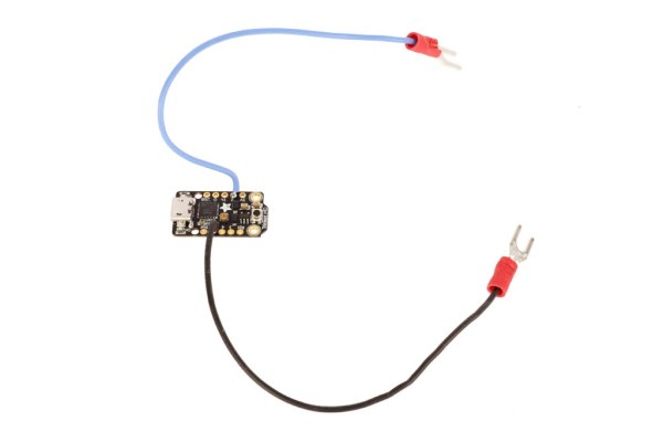
Solder the black wire to ground.
Solder the other wire to pin 2.
Note: If you don’t know how to solder, you can learn how in my Intro to Soldering instructable.
Step 5: Insert the USB

Find the enclosure’s rubber grommet.
With a razor blade, cut a small slit large enough to pass the end of USB cable through, and then do so.
Step 6: Plug in the USB
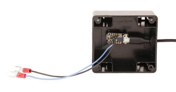
Mount the rubber grommet in the enclosure and then plug the USB cable into the Trinket M0.
Step 7: Replace the Switch (optional)
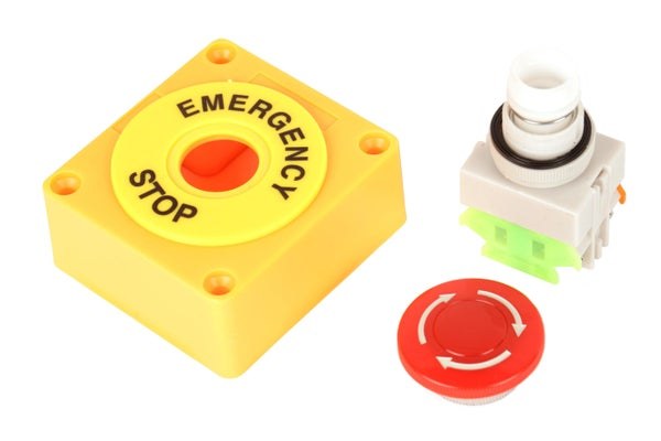
The emergency switch assembly comes with a latching switch. This means when you press it down, the switch locks into place and stays there until you twist and release it.
I wanted my button to return on its own. Thus, I decided to replace it with a momentary spring-return switch.
In order to do this, I just disassembled the latching switch and remove it from the enclosure. I then disassembled and installed the momentary switch instead.
Step 8: Wire the Switch
There are two sets of connections inside the switch. One is normally open (not connected) and one is normally closed (connected). We want to connect the two wires to the normally open connection. That way, when the switch is pressed the connection closes.
Usually these connections are marked. In my switch it wasn’t marked, but the enclosure was clear and I could see which connection was the one that was not normally connected to terminals.
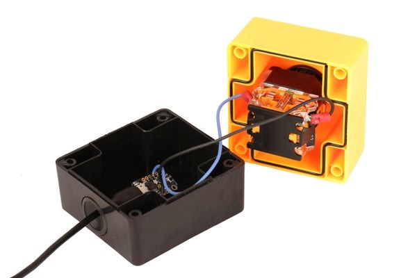
I attached the spade terminals from the circuit board to these two terminals using their mounting screws.
Note:If you end up getting this wrong, no worries. Just switch the wires to the other set of terminals.
Step 9: Close the Case
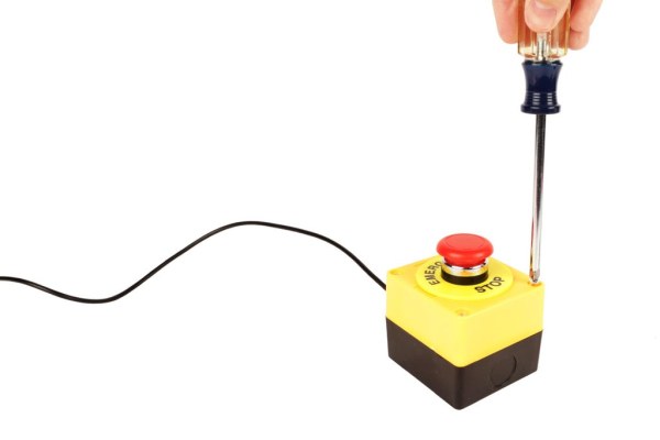
Put the lid on the enclosure and fasten it shut with its mounting screws.
Source: Easy Zoom Quit Button