Summary of How to Build a Robotic Hand with Haptic Feedback using Arduino
The author built a robotic hand with haptic feedback for a science fair, inspired by an Instructables project. The system allows the controller to "feel" what the robotic hand touches using force-sensitive resistors and vibrating motors. Constructed primarily from laser-cut acrylic, the hand features four-bar linkages in each finger driven by hobby servos. The project uses an Arduino Mega for control and is designed for continuous improvement and future modifications.
Parts used in the Robotic Hand with Haptic Feedback:
- A2-70 bolts (beveled and regular heads)
- Nylon-insert lock nuts
- 4-40 x 1/2" machine screws
- 2-56 Threaded ball links
- Jumbo paperclips
- #4S washers
- Arduino Mega
- FSR Flexible Resistors
- Mini Vibrating Motors
- PCB Screw Terminals
- 22k and 10k Resistors
- 24AWG twisted pair wire
- Hobby Servos
- 5mm Acrylic
- Duct Tape
- Glove
- Heat-Shrink Tubing
- Thread
For science fair this year, I felt like building something instead of doing an experiment. All I needed to do was look around Instructables for a project idea. I was inspired by njkl44’s robotic hand since it reminds me so much of stuff out of science fiction movies. My goal was to create a system of haptic feedback from a robotic hand like that. The system provides a way for the person controlling the hand to “feel” what the robotic hand is feeling. I thought that this was an excellent project since it gave me something to do for science fair, and it provided me with a platform for constant development. In other words, I will not stop working on it. I will always try to come back to it, so I can make various improvements or redesign it every now and then.
njkl44’s robotic hand:
http://www.instructables.com/id/Arduino-Wireless-Animatronic-Hand/
Step 1: Materials and Tools
Materials:
Per Finger:
A2-70 bolts- 3 with a beveled head and 4 with a regular head for each finger
Nylon-insert lock nuts for the bolts
4-40 x 1/2″ machine screw and matching nut
2-56 Threaded ball link (for connecting the finger to the servo)
Jumbo paperclip (used for connecting the ball links)
(x28) #4S washers
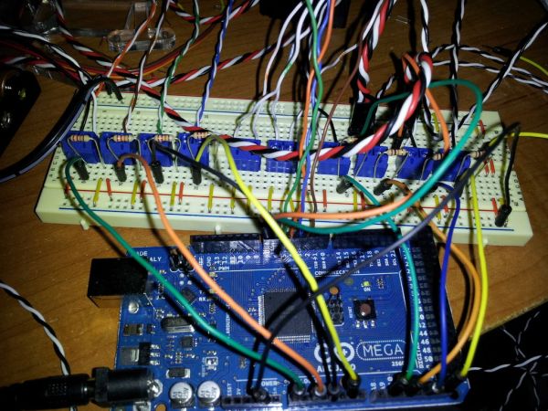
Electronics:
Arduino Mega
(x4) FSR
(x4) 4.5″ Flexible Resistor
(x4) Mini Vibrating Motors
(x10) PCB Screw Terminals
(x4) 22k Resistors
(x4) 10k Resistors
24AWG wire in a twisted pair (the pairs make it easier to manage the wires)
(x4) Hobby Servos
Misc. breadboarding equipment
6V Power Source (I used a 4xAA battery holder)
Other:
5mm Acrylic
Duct Tape
Golve
Heat-Shrink Tubing
Thread
Tools:
Laser Cutter
Dremel
Drill Press
Hot Glue Gun
Soldering Iron
Safety Glasses
Needle
Step 2: The Design
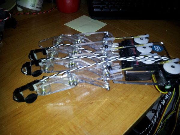
For the parts, I was able to get them laser cut out of acrylic at my local hackerspace, HeatSync Labs. Acrylic is an excellent material for smaller loads and basic testing, but if there is any sort of major strain on the finger, you run the risk of snapping the parts. Instead of acrylic, it would be better to get the parts made out of metal for larger loads.
There is no scale on the .dxf files. For the fingers, the holes should be 2.8mm. For the palm, the rectangles are 20x40mm. I used Hitec HS-322 HD servos, and they fit perfectly. You will have to take the servo case off and put it back together in the hand since there is a small lip where the wires come out.
 hand.dxf1 KBhand_plate.dxf49 KB
Step 3: Put the Fingers Together
Originally, the fingers used 4-40 bolts for all of the holes, but since the metric bolts fit better, I swapped all of the bolts out.
I needed to bevel the inside holes on the parts in order for the beveled bolts to sit flush with the surface of the acrylic. To do this, I used a drill press with a drill bit the same size as the beveled heads. I also cut the bolts down a bit to prevent them from catching between the fingers.
CUT THE BOLTS CAREFULLY. This can cause trouble if done without safety glasses and gloves. Also remember to put on the regular nuts before cutting the bolts and take them off afterwards. This will keep the threading from deforming when you put the lock nuts on.
For putting the finger together:
Put the beveled bolts on first.
Then the other bolts in any order.
Each bolt also gets its own washer and lock nut
(x4) FSR
(x4) 4.5″ Flexible Resistor
(x4) Mini Vibrating Motors
(x10) PCB Screw Terminals
(x4) 22k Resistors
(x4) 10k Resistors
24AWG wire in a twisted pair (the pairs make it easier to manage the wires)
(x4) Hobby Servos
Misc. breadboarding equipment
6V Power Source (I used a 4xAA battery holder)
For more detail: How to Build a Robotic Hand with Haptic Feedback using Arduino
- What inspired the creator to build this robotic hand?
The creator was inspired by njkl44's robotic hand on Instructables because it resembled science fiction movies. - How does the system provide haptic feedback?
The system uses Force Sensitive Resistors and Mini Vibrating Motors to let the person controlling the hand feel what the robotic hand touches. - What material was used for the finger parts and why might it be changed?
Laser cut 5mm Acrylic was used for smaller loads, but metal would be better if there is major strain to prevent snapping. - Which servo model fits perfectly into the hand design?
Hitec HS-322 HD servos fit perfectly, though their cases must be removed and reassembled to route wires. - What safety precautions are required when cutting bolts?
Safety glasses and gloves must be worn, and regular nuts should be put on before cutting to protect threading. - Why were metric bolts swapped in for the original design?
Metric bolts were swapped in because they fit the holes better than the originally specified 4-40 bolts. - What power source was used for the electronics?
A 6V Power Source was used, specifically a 4xAA battery holder. - How many fingers does the robotic hand have?
The project description lists materials and components for four fingers.