Summary of HAVE FUN WITH BICOLOR MATRIX 32×32
This article details the DIY construction of a 32x32 bicolor LED matrix controlled by a NodeMCU ESP8266 using the B.A.M scanning method. The author provides code examples for real-time clock projects, including rainbow letters and Tetris animations. The project involves etching custom PCBs for row and column scanning circuits and connecting various logic chips and transistors to manage the 1024 red and green LEDs with a 1/16 scan rate to minimize flickering.
Parts used in the 32x32 Bicolor LED Matrix:
- Arduino Mega 2560 (Optional)
- NodeMCU ESP8266 V1.0
- Bicolor Led Matrix 8x8 Common Anode (Code: 2088ABEG-5)
- 74HC595 - 8-Bit Shift Register DIP-16
- ULN2803 - Transistor Array-8 NPN IC DIP-18
- 2N3904 - TO-92 NPN General Purpose Transistor
- TIP42C - POWER TRANSISTOR PNP 100V 6A
- 74HC238 - 3 to 8 Line Decoder
- 0.1uF Capacitors
- R10 Resistors
- R1K Resistors
- R10K Resistors
- 5x7 Double Sided Printed Prototyping Board
- XH2.54mm Wire Cables (8P, 4P, 5P)
- Male and Female 40pin Header Socket Row Strip PCB Connectors
- Acrylic Plate
- Power Supply 5V, 10A or 40A
- 9V Battery and battery clip connector
Today I will share following topics base on a bicolor matrix led 32×32:
- D.I.Y a bicolor led matrix 32×32.
- How to control led board above with NodeMCU ESP8266 via B.A.M method.
- Introduce and share my code for some cool real time clock projects with this bicolor led board.
Let’s start with some videos:
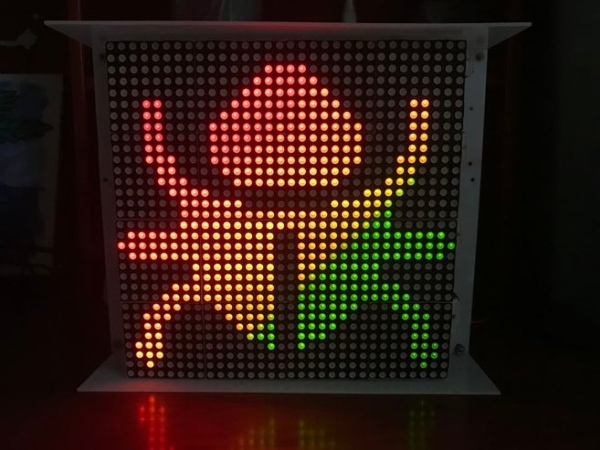
- Rainbow letters and images: is controlled by NODEMCU.
Handwritten Clock Version 2:
Tetris clock: is referenced from TobiasB48
Handwritten Clock Version 1:
Morphing Digital Clock: is referenced from HariFun.
Step 1: MATERIAL LIST
Main components include:
- 1pcs x Arduino Mega 2560. (Optional)
- 1pcs x NodeMCU ESP8266 V1.0.
- 16pcs x Bicolor Led Matrix 8×8, common anode (Code: 2088ABEG-5), dimension 60x60mm.
- 16pcs x 74HC595 – 8-Bit Shift Register DIP-16.
- 16pcs x ULN2803 – Transistor Array-8 NPN IC DIP-18.
- 16pcs x 2N3904 – TO-92 NPN General Purpose Transistor. (or 2N2222)
- 16pcs x TIP42C – POWER TRANSISTOR PNP 100V 6A.
- 2pcs x 74HC238 – 3 to 8 Line Decoder.
- 16pcs x 0.1uF Capacitors.
- 200pcs x R10.
- 20pcs x R1K.
- 40pcs x R10K.
- 1pcs x 5×7 Double Sided Printed Prototyping Board.
- 20pcs x XH2.54mm – 8P 20cm Wire Cable Double Connector.
- 4pcs x XH2.54mm – 4P 20cm Wire Cable Double Connector.
- 2pcs x XH2.54mm – 5P 20cm Wire Cable Double Connector.
- 10pcs x Male 40pin 2.54mm Header Socket Row Strip PCB Connector.
- 10pcs x Female 40pin 2.54mm Header Socket Row Strip PCB Connector.
- Some wires, acrylic plate.
- Power supply 5V, 10A. (I used a power supply 5V-40A for this project)
- 1 set of 9 V battery and battery clip connector (to check the led).
Step 2: SCHEMATIC
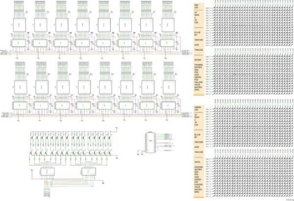
This is the circuit diagram of the whole project; it is a quite big file and you can download high resolution PDF file HERE. With this overall schematic, we will easily understand how to scan rows and columns for led matrices, as well as, how to apply the 4-bit BAM method during row and column scanning.
On the circuit diagram, I separated 32×32 = 1024 red and 32×32 = 1024 green LEDs in groups and connect default matrix pin in Fritzing to rows and columns buses. You have to connect color pins properly according to the specifications after purchasing bicolor led matrix.
NODECU pins are used as below:
// PINS USING ON NODEMCU
#define blank_pin	D8  // BLANK PIN - 74HC595
#define latch_pin	D4  // LATCH PIN - 74HC595
#define clock_pin	D5  // CLOCK PIN - 74HC595
#define data_pin	D7  // DATA PIN - 74HC595

#define RowA_Pin	D0  // A PIN - 74HC238
#define RowB_Pin	D1  // B PIN - 74HC238
#define RowC_Pin	D2  // C PIN - 74HC238
#define RowD_Pin	D3  // D PIN - 74HC238
//#define OE_Pin	D8  // ENABLE OUTPUT PIN - 74HC238 (Connect to blank_pin).
Note that:
- I used 5 signals to control 2x74HC238 for implementing one 4 to 16 decoder. Then these 16 outputs will control 32 rows of bicolor led matrix through PNP and NPN transistors. In other words, my led panel have 1/16 scan rate, so only one row of 16 is on at a time. You can see how scan pattern a 32×32 led board with scan rate 1/16 looks like, at this link: https://www.sparkfun.com/sparkx/blog/2650
- OE PIN – 74HC238 and BLANK PIN – 74HC595 are both connect to NODEMCU – D8 pin. This is an important key to minimize flickering and noise because we only enable the OE pin (Output Enable) for 74HC595 (columns) and 74HC238 (rows) when we needed. I have also tested this Led board on Arduino Mega 2560 with 2 OE signals which are individually controlled, one for 74HC595 and the remaining signal for 74HC238. It also gave good results. Check detail at STEP 5.
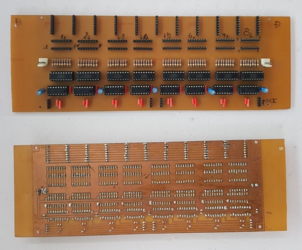
Step 3: PCB BOARD DESIGN AND ETCHING
You can download as attached links for following schematics and PCB files:
1. Row scanning circuit schematic and Eagle PCB real size.
2. Column scanning circuit schematic and Eagle PCB real size.
3. Led matrix board 32×32 schematic and Eagle PCB real size for 16×32 led board.
I etched myself these printed circuit boards at home by Toner Transfer Method and concentrated ferrous chloride. The pictures below are the results that I did:
- Column Scanning Board: we need 2 sets of column scanning PCB for RED and GREEN color.
Read more: HAVE FUN WITH BICOLOR MATRIX 32×32
- How is the 32x32 LED board controlled?
The board is controlled by a NodeMCU ESP8266 via the B.A.M method. - What is the scan rate of the LED panel described?
The LED panel has a 1/16 scan rate where only one row of 16 is on at a time. - Which pins on the NodeMCU are used for the 74HC595 shift register?
D8 is used for the blank pin, D4 for latch, D5 for clock, and D7 for data. - How many signals are used to control the two 74HC238 decoders?
Five signals are used to control the two 74HC238 decoders to implement a 4 to 16 decoder. - What components are used to connect the decoder outputs to the LED rows?
PNP and NPN transistors are used to connect the 16 decoder outputs to the 32 rows of the bicolor LED matrix. - Why are the OE PIN and BLANK PIN connected to the same NodeMCU pin?
Connecting them to the same pin minimizes flickering and noise by enabling outputs only when needed. - Can this project be run on an Arduino Mega 2560 instead of NodeMCU?
Yes, the author tested the board on an Arduino Mega 2560 with individually controlled OE signals. - How were the printed circuit boards manufactured for this project?
The boards were etched at home using the Toner Transfer Method and concentrated ferrous chloride. - What specific video projects are referenced in the article?
Referenced projects include Rainbow letters, Handwritten Clock Version 1 and 2, Tetris clock, and Morphing Digital Clock. - How are the red and green LEDs separated in the schematic?
The schematic separates the 1024 red and 1024 green LEDs into groups connected to rows and columns buses.