Summary of Hack an old iPod using an Android and an Arduino
This tutorial guides turning an old iPod-based music player into a Bluetooth-controlled docking station using an Arduino. The project enables automatic music play/pause based on proximity, call pause, and alarm features without soldering, costing under $25. It connects the iPod directly to the stereo for error-free audio and uses an HC-05 Bluetooth module for Android device control. The key components include an Arduino board, a 30-pin iPod dock extender cable supporting audio/video, resistors, a Bluetooth module, and the MuseHack Android app.
Parts used in the MuseHack Station project:
- Arduino Board (Uno, Mega, or compatible)
- 30-pin iPod/iPhone/iPad device
- 30-pin iPod dock extender cable (audio/video capable)
- HC-05 or HC-06 Bluetooth Serial breakout board
- 2k Ohm resistors (2 pieces)
- 4.68k Ohm resistors (2 pieces)
- 500k Ohm resistor (1 piece)
- Breadboard
- Jumper wires
- Android powered device (for app control)
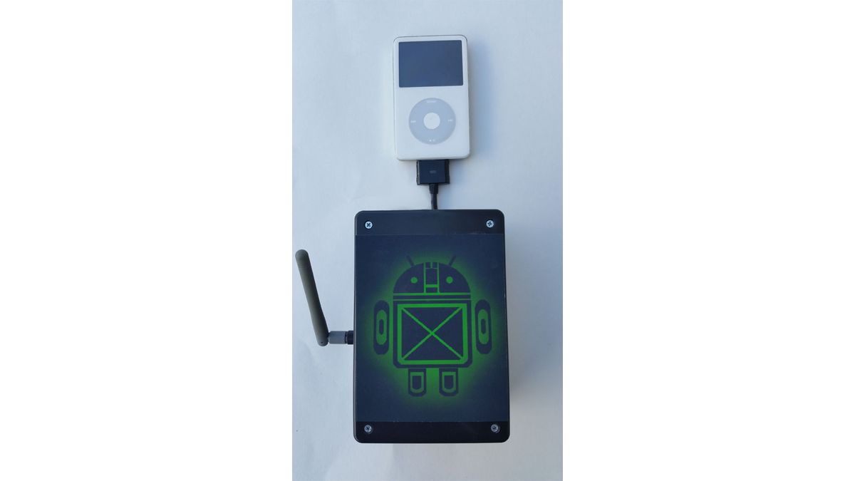
This tutorial shows you how to use an Arduino to turn that old dusty music player into a Bluetooth controlled docking station.
Even if it has a cracked screen or a dead battery it can still be used.
The following instructions will show you how use an Arduino and a couple of cheap parts to set up a MuseHack station NO SOLDERING REQUIRED!!!
This project can be built for under $25 which includes buying an Arduino.
Just leave the old Ipod plugged into the stereo and your music will start to play when you walk in the door.
The Arduino acts as a liaison between the iPod and your Droid.
Features Include:
- Auto Connect – If set, your phone will automatically connect to your MuseHack Station
- Auto Play – Walk in the door and your music will start playing
- Auto Pause – Leave your house and the music pauses for you
- In-Call Pause – Automatically pauses when a call is in session
- Alarm – Wake up to your own music blasting through the stereo
Since the iPod device is connected directly to your stereo, it eliminates any error that can occur when streaming the music to a separate device.
iPod, iPad, and iPhone are trademarks of Apple Inc., registered in the U.S. and other countries.
Step 1: Cut To The Chase
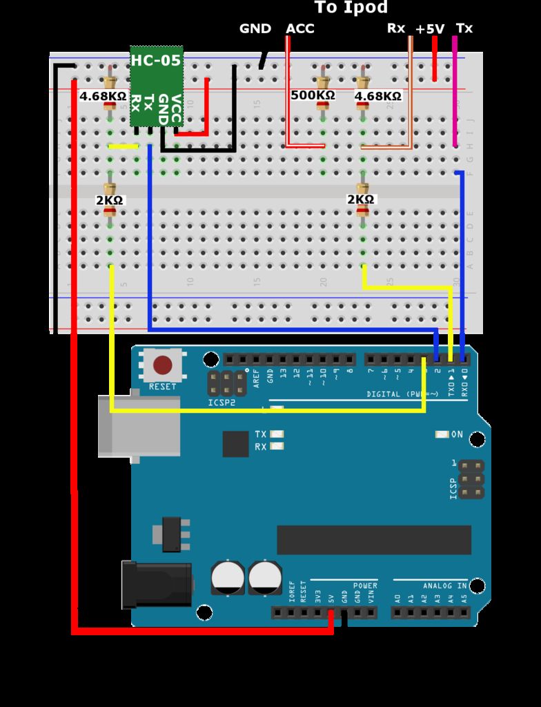
If you want to just get after it, you can download the code and wire it according to the above image.
The wire colors correspond to the cable suggested by this tutorial.
- +5V Pin 23 Red (No Stripe)
- GND Pin 16 Black (No Stripe)
- Rx Pin 13 Brown (With Stripe)
- Tx Pin 12 Purple (No Stripe)
- ACC Pin 21 Red (With Stripe)
Here is the app:
Full Version:
http://play.google.com/store/apps/details?id=com.e…
Lite Version:
http://play.google.com/store/apps/details?id=com.e…
The Bluetooth pairing pin is 1234
For Arduino Uno – The digital pins 0 and 1 (Rx and Tx) must be clear when uploading the sketch.
This is really all you need to complete this project. The rest of this tutorial just rambles on a bit.
Step 2: What you will need
To start, you will need a fully functional Android powered device and at least a semi functional iPod, iPad or iPhone that uses the 30 pin connector. Having music on it helps
The ebay links provided are the cheapest of these items I could find and may be outdated but can point you in the right direction. For reliability I have also provided a few amazon links.
- 30 pin iPod/iPhone/iPad Device
- Android Device
- Arduino (Uno, Mega, or any Arduino compatible board)
http://www.amazon.com/Development-Board-ATmega328P…
http://www.ebay.com/itm/UNO-R3-Development-Board-M…
- 30 pin iPod dock extender cable (MUST BE ABLE TO PROVIDE AUDIO/VIDEO, NOT JUST DATA AND POWER) If you get the one used in this tutorial it will make your life a bit easier as the wire colors will match
http://www.amazon.com/Connector-Extender-Extension…
http://www.ebay.com/itm/30-PIN-Dock-Extender-Exten…
- HC-05/HC-06 Bluethooth Serial breakout board (AKA JY-MCU)
http://www.amazon.com/Innogear-Wireless-Bluetooth-…
http://www.ebay.com/itm/Wireless-Bluetooth-RF-Tran…
- 2k Ohm (2 Qty), 4.68k Ohm (2 Qty), 500k Ohm (1 Qty) Resistors
Link is for a whole mess of resistors of which include the above
http://www.ebay.com/itm/400-Pcs-1-4W-1-20-Kinds-Ea…
- MuseHack App for Android
Full Version:
http://play.google.com/store/apps/details?id=com.e…
Lite Version:
http://play.google.com/store/apps/details?id=com.e…
- Breadboard
http://www.ebay.com/itm/Mini-Nickel-Plating-Breadb…
http://www.ebay.com/itm/170-400-700-830Tie-Points-…
http://www.amazon.com/BB400-Solderless-Plug–Bread…
- Jumper wires
http://www.ebay.com/itm/Male-to-Male-Solderless-Fl…
http://www.amazon.com/40pcs-2-54mm-Breadboard-Jump…
Tools
- Wire Strippers/Cutters
This is really the only tool that is required.
Not Required but may be helpful:
- Arduino/breadboard
- mounting plate or project box
Radioshack actually has a decent selection of project boxes The box used in the tutorial is about 4 x 6 x 2 in.
- Electrical tape
- Binder clip
- Soldering iron
- Multimeter
Step 3: Communication
Both the iPod and the HC-05/06 Bluetooth module use serial communication to talk to the Arduino.
The Atmel MCUs used on the Arduino come with a UART (Universal Asynchronous Receiver/Transmitter) built in.
The UART is a peice of hardware that will take bytes of data and sequentially transmit them in single bits. The receiving UART will reassemble the bytes.
For more on UART/USART
http://en.wikipedia.org/wiki/Universal_asynchronou…
If you are using an Arduino with only one serial port (ie. Uno, Leonardo), the SoftwareSerial library will be used.
If you are using the Mega, multiple serial ports are supported and there is no need for the SoftwareSerial library.
The Arduino code will adapt if using a board with multiple serial ports. This will be covered later in the code section.
Step 4: The HC-05/HC-06 Bluetooth Module
From here on out I will be referring to this Bluetooth device as the HC-05.
You will not have to worry about the details of the HC-05 for building this project since the factory settings are used. Just plug and play.
The main difference between the HC-05 and HC-06 is its ability to be set from the slave role to the master role. All HC-XX modules, where XX is an even number, come from the factory in the slave role and cannot be changed. On the other hand, all modules, where XX is an odd number, can be set to the master role using AT commands. The HC-06 and other even numbered modules also have a limited number of AT commands available for setting preferences compared to their odd numbered counterparts.
For more information on Bluetooth technology, the Bluetooth website is very informative:
Step 5: The iPod Devices
The iPod is a versatile little mp3 player and can be used with many different accessories. Those 30 pin connectors hold pins for Docking stations, firewires, USB and more. In this case we are using the Serial Rx and Tx pins.
That dock extender cable is used because it has connections for those pins as opposed to the normal usb connection which only has +USB data -USB data VCC and GND.
The connector is a JAE DD1 30 pin connector.
This project will use the following 5 pins:
- +5V – Pin 23
- GND – Pin 16
- Rx – Pin 13
- Tx – Pin 12
- Acc – Pin 21
The Acc pin is pulled low through a resistor, and depending on the resistance, the iPod will know what type of accessory it is attached to and how to communicate accordingly.
For more detail: Hack an old iPod using an Android and an Arduino