A gesture-detecting wearable sleeve that can direct a robot in different directions.
Things used in this project
Hardware components | ||||||
 |
| × | 1 | |||
| × | 1 | ||||
 |
| × | 1 | |||
| × | 1 | ||||
 |
| × | 1 | |||
 |
| × | 4 | |||
Software apps and online services | ||||||
 |
| |||||
 |
| |||||
 |
| |||||
Hand tools and fabrication machines | ||||||
 |
| |||||
Story
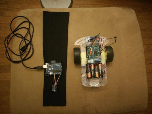
In this project, we have created a sleeve that can detect motion in several different directions and remotely move a robot. This is the first part of a larger project to create a wearable that can detect more subtle motions of the hand and direct a UAV. Ultimately, this project aims to eliminate the interface between user and robot. Using the motions of the hand to control a UAV or robot is intuitive, natural, and more precise than using manual controls. It will also not require as much training, being possibly useful in military, farming, film, and many other applications.
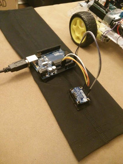
There are two main components to this project. The first component is the sleeve and orientation sensing. Here, the sleeve has an orientation sensor and Arduino UNO sewn into it. The UNO is also connected to a computer that runs a UWApp and serially receives the information sensed on the UNO pins.
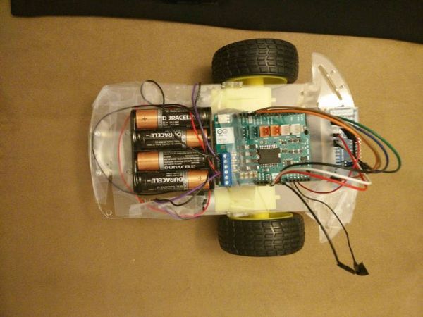
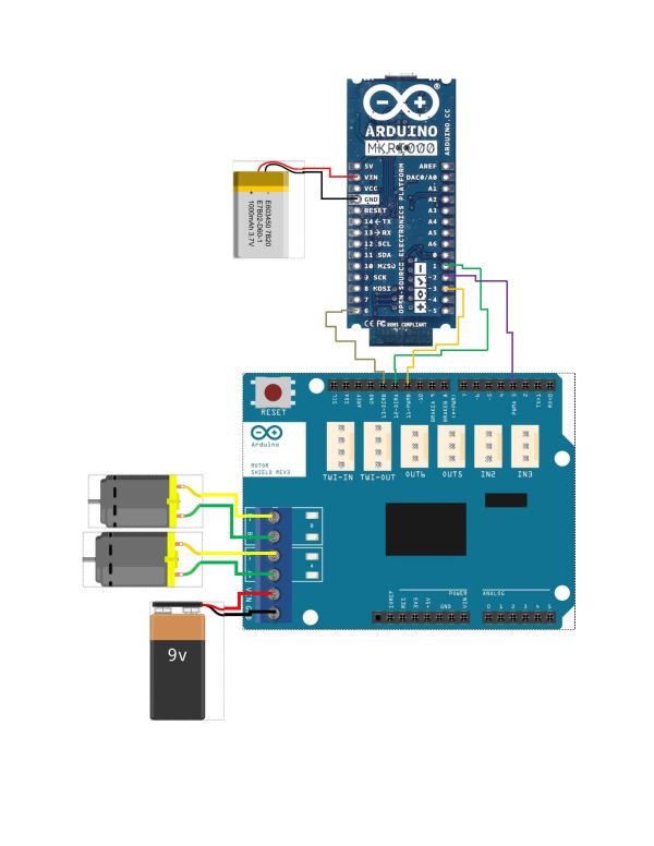
The second component is the robot. The robot has two motors that are driven by an Arduino Motor Shield. The Motor Shield in turn is driven by an Arduino MKR1000. The GPIO pins on the MKR1000 are remotely set through WiFi inside the UWApp running on the computer.
The App can correctly identify and set the following motions:
– Stopping the robot when the hand is by the side of the body.
-Starting the robot when the hand is stretched out in front of the body.
-Moving the robot to the right or left depending on the direction of the arm with respect to where the robot was started.
-Reversing the direction of the robot when the arm is at 90 degree angle and facing up with respect to the body.
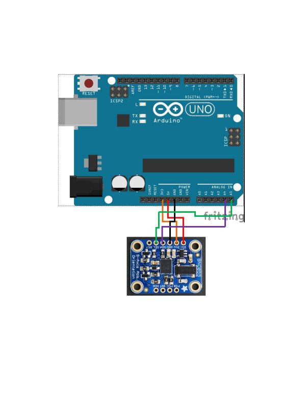
Schematics
Sensor Circuit
Robot Circuit
Code
#include <Wire.h>
#include <Adafruit_Sensor.h>
#include <Adafruit_BNO055.h>
#include <utility/imumaths.h>

/* This driver uses the Adafruit unified sensor library (Adafruit_Sensor),
   which provides a common 'type' for sensor data and some helper functions.

   To use this driver you will also need to download the Adafruit_Sensor
   library and include it in your libraries folder.

   You should also assign a unique ID to this sensor for use with
   the Adafruit Sensor API so that you can identify this particular
   sensor in any data logs, etc.  To assign a unique ID, simply
   provide an appropriate value in the constructor below (12345
   is used by default in this example).

   Connections
   ===========
   Connect SCL to analog 5
   Connect SDA to analog 4
   Connect VDD to 3-5V DC
   Connect GROUND to common ground

   History
   =======
   2015/MAR/03  - First release (KTOWN)
   2015/AUG/27  - Added calibration and system status helpers
*/

/* Set the delay between fresh samples */
#define BNO055_SAMPLERATE_DELAY_MS (100)

Adafruit_BNO055 bno = Adafruit_BNO055(55);

/**************************************************************************/
/*
    Displays some basic information on this sensor from the unified
    sensor API sensor_t type (see Adafruit_Sensor for more information)
*/
/**************************************************************************/
void displaySensorDetails(void)
{
  sensor_t sensor;
  bno.getSensor(&sensor);
  Serial.println("------------------------------------");
  Serial.print  ("Sensor:       "); Serial.println(sensor.name);
  Serial.print  ("Driver Ver:   "); Serial.println(sensor.version);
  Serial.print  ("Unique ID:    "); Serial.println(sensor.sensor_id);
  Serial.print  ("Max Value:    "); Serial.print(sensor.max_value); Serial.println(" xxx");
  Serial.print  ("Min Value:    "); Serial.print(sensor.min_value); Serial.println(" xxx");
  Serial.print  ("Resolution:   "); Serial.print(sensor.resolution); Serial.println(" xxx");
  Serial.println("------------------------------------");
  Serial.println("");
  delay(500);
}

/**************************************************************************/
/*
    Display some basic info about the sensor status
*/
/**************************************************************************/
void displaySensorStatus(void)
{
  /* Get the system status values (mostly for debugging purposes) */
  uint8_t system_status, self_test_results, system_error;
  system_status = self_test_results = system_error = 0;
  bno.getSystemStatus(&system_status, &self_test_results, &system_error);

  /* Display the results in the Serial Monitor */
  Serial.println("");
  Serial.print("System Status: 0x");
  Serial.println(system_status, HEX);
  Serial.print("Self Test:     0x");
  Serial.println(self_test_results, HEX);
  Serial.print("System Error:  0x");
  Serial.println(system_error, HEX);
  Serial.println("");
  delay(500);
}

/**************************************************************************/
/*
    Display sensor calibration status
*/
/**************************************************************************/
void displayCalStatus(void)
{
  /* Get the four calibration values (0..3) */
  /* Any sensor data reporting 0 should be ignored, */
  /* 3 means 'fully calibrated" */
  uint8_t system, gyro, accel, mag;
  system = gyro = accel = mag = 0;
  bno.getCalibration(&system, &gyro, &accel, &mag);

  /* The data should be ignored until the system calibration is > 0 */
  Serial.print("\t");
  if (!system)
  {
    Serial.print("! ");
  }

  /* Display the individual values */
  Serial.print("Sys:");
  Serial.print(system, DEC);
  Serial.print(" G:");
  Serial.print(gyro, DEC);
  Serial.print(" A:");
  Serial.print(accel, DEC);
  Serial.print(" M:");
  Serial.print(mag, DEC);
}

/**************************************************************************/
/*
    Arduino setup function (automatically called at startup)
*/
/**************************************************************************/
void setup(void)
{
  Serial.begin(9600);
  Serial.println("Orientation Sensor Test"); Serial.println("");

  /* Initialise the sensor */
  if(!bno.begin())
  {
    /* There was a problem detecting the BNO055 ... check your connections */
    Serial.print("Ooops, no BNO055 detected ... Check your wiring or I2C ADDR!");
    while(1);
  }

  delay(1000);

  /* Display some basic information on this sensor */
  displaySensorDetails();

  /* Optional: Display current status */
  displaySensorStatus();

  bno.setExtCrystalUse(true);
}

/**************************************************************************/
/*
    Arduino loop function, called once 'setup' is complete (your own code
    should go here)
*/
/**************************************************************************/
void loop(void)
{
  /* Get a new sensor event */
  sensors_event_t event;
  bno.getEvent(&event);

  /* Display the floating point data */
  Serial.print("X: ");
  Serial.print(event.orientation.x, 4);
  Serial.print("\tY: ");
  Serial.print(event.orientation.y, 4);
  Serial.print("\tZ: ");
  Serial.print(event.orientation.z, 4);

  /* Optional: Display calibration status */
  displayCalStatus();

  /* Optional: Display sensor status (debug only) */
  //displaySensorStatus();

  /* New line for the next sample */
  Serial.println("");

  /* Wait the specified delay before requesting nex data */
  delay(BNO055_SAMPLERATE_DELAY_MS);
}
StandardFirmataWifi
C/C++
/*
  Firmata is a generic protocol for communicating with microcontrollers
  from software on a host computer. It is intended to work with
  any host computer software package.

  To download a host software package, please clink on the following link
  to open the list of Firmata client libraries your default browser.

  https://github.com/firmata/arduino#firmata-client-libraries

  Copyright (C) 2006-2008 Hans-Christoph Steiner.  All rights reserved.
  Copyright (C) 2010-2011 Paul Stoffregen.  All rights reserved.
  Copyright (C) 2009 Shigeru Kobayashi.  All rights reserved.
  Copyright (C) 2009-2016 Jeff Hoefs.  All rights reserved.
  Copyright (C) 2015-2016 Jesse Frush. All rights reserved.

  This library is free software; you can redistribute it and/or
  modify it under the terms of the GNU Lesser General Public
  License as published by the Free Software Foundation; either
  version 2.1 of the License, or (at your option) any later version.

  See file LICENSE.txt for further informations on licensing terms.

  Last updated by Jeff Hoefs: January 10th, 2016
*/

/*
  README

  StandardFirmataWiFi is a WiFi server application. You will need a Firmata client library with
  a network transport in order to establish a connection with StandardFirmataWiFi.

  To use StandardFirmataWiFi you will need to have one of the following
  boards or shields:

  - Arduino WiFi Shield (or clone)
  - Arduino WiFi Shield 101
  - Arduino MKR1000 board (built-in WiFi 101)
  - Adafruit HUZZAH CC3000 WiFi Shield (support coming soon)

  Follow the instructions in the wifiConfig.h file (wifiConfig.h tab in Arduino IDE) to
  configure your particular hardware.

  Dependencies:
  - WiFi Shield 101 requires version 0.7.0 or higher of the WiFi101 library (available in Arduino
    1.6.8 or higher, or update the library via the Arduino Library Manager or clone from source:
    https://github.com/arduino-libraries/WiFi101)

  In order to use the WiFi Shield 101 with Firmata you will need a board with at least
  35k of Flash memory. This means you cannot use the WiFi Shield 101 with an Arduino Uno
  or any other ATmega328p-based microcontroller or with an Arduino Leonardo or other
  ATmega32u4-based microcontroller. Some boards that will work are:

  - Arduino Zero
  - Arduino Due
  - Arduino 101
  - Arduino Mega

  NOTE: If you are using an Arduino WiFi (legacy) shield you cannot use the following pins on
  the following boards. Firmata will ignore any requests to use these pins:

  - Arduino Uno or other ATMega328 boards: (D4, D7, D10, D11, D12, D13)
  - Arduino Mega: (D4, D7, D10, D50, D51, D52, D53)
  - Arduino Due, Zero or Leonardo: (D4, D7, D10)

  If you are using an Arduino WiFi 101 shield you cannot use the following pins on the following
  boards:

  - Arduino Due or Zero: (D5, D7, D10)
  - Arduino Mega: (D5, D7, D10, D50, D52, D53)
*/

#include <Servo.h>
#include <Wire.h>
#include <Firmata.h>

/*
 * Uncomment the #define SERIAL_DEBUG line below to receive serial output messages relating to your
 * connection that may help in the event of connection issues. If defined, some boards may not begin
 * executing this sketch until the Serial console is opened.
 */
#define SERIAL_DEBUG
#include "utility/firmataDebug.h"

/*
 * Uncomment the following include to enable interfacing with Serial devices via hardware or
 * software serial. Note that if enabled, this sketch will likely consume too much memory to run on
 * an Arduino Uno or Leonardo or other ATmega328p-based or ATmega32u4-based boards.
 */
//#include "utility/SerialFirmata.h"

// follow the instructions in wifiConfig.h to configure your particular hardware
#include "wifiConfig.h"

#define I2C_WRITE                   B00000000
#define I2C_READ                    B00001000
#define I2C_READ_CONTINUOUSLY       B00010000
#define I2C_STOP_READING            B00011000
#define I2C_READ_WRITE_MODE_MASK    B00011000
#define I2C_10BIT_ADDRESS_MODE_MASK B00100000
#define I2C_END_TX_MASK             B01000000
#define I2C_STOP_TX                 1
#define I2C_RESTART_TX              0
#define I2C_MAX_QUERIES             8
#define I2C_REGISTER_NOT_SPECIFIED  -1

// the minimum interval for sampling analog input
#define MINIMUM_SAMPLING_INTERVAL   1

#define WIFI_MAX_CONN_ATTEMPTS      3

/*==============================================================================
 * GLOBAL VARIABLES
 *============================================================================*/

#ifdef FIRMATA_SERIAL_FEATURE
SerialFirmata serialFeature;
#endif

#ifdef STATIC_IP_ADDRESS
IPAddress local_ip(STATIC_IP_ADDRESS);
#endif

int wifiConnectionAttemptCounter = 0;
int wifiStatus = WL_IDLE_STATUS;

/* analog inputs */
int analogInputsToReport = 0;      // bitwise array to store pin reporting

/* digital input ports */
byte reportPINs[TOTAL_PORTS];       // 1 = report this port, 0 = silence
byte previousPINs[TOTAL_PORTS];     // previous 8 bits sent

/* pins configuration */
byte portConfigInputs[TOTAL_PORTS]; // each bit: 1 = pin in INPUT, 0 = anything else

/* timer variables */
unsigned long currentMillis;        // store the current value from millis()
unsigned long previousMillis;       // for comparison with currentMillis
unsigned int samplingInterval = 19; // how often to sample analog inputs (in ms)

/* i2c data */
struct i2c_device_info {
  byte addr;
  int reg;
  byte bytes;
  byte stopTX;
};

/* for i2c read continuous mode */
i2c_device_info query[I2C_MAX_QUERIES];

byte i2cRxData[32];
boolean isI2CEnabled = false;
signed char queryIndex = -1;
// default delay time between i2c read request and Wire.requestFrom()
unsigned int i2cReadDelayTime = 0;

Servo servos[MAX_SERVOS];
byte servoPinMap[TOTAL_PINS];
byte detachedServos[MAX_SERVOS];
byte detachedServoCount = 0;
byte servoCount = 0;

boolean isResetting = false;

/* utility functions */
void wireWrite(byte data)
{
#if ARDUINO >= 100
  Wire.write((byte)data);
#else
  Wire.send(data);
#endif
}

byte wireRead(void)
{
#if ARDUINO >= 100
  return Wire.read();
#else
  return Wire.receive();
#endif
}

/*==============================================================================
 * FUNCTIONS
 *============================================================================*/

void attachServo(byte pin, int minPulse, int maxPulse)
{
  if (servoCount < MAX_SERVOS) {
    // reuse indexes of detached servos until all have been reallocated
    if (detachedServoCount > 0) {
      servoPinMap[pin] = detachedServos[detachedServoCount - 1];
      if (detachedServoCount > 0) detachedServoCount--;
    } else {
      servoPinMap[pin] = servoCount;
      servoCount++;
    }
    if (minPulse > 0 && maxPulse > 0) {
      servos[servoPinMap[pin]].attach(PIN_TO_DIGITAL(pin), minPulse, maxPulse);
    } else {
      servos[servoPinMap[pin]].attach(PIN_TO_DIGITAL(pin));
    }
  } else {
    Firmata.sendString("Max servos attached");
  }
}

void detachServo(byte pin)
{
  servos[servoPinMap[pin]].detach();
  // if we're detaching the last servo, decrement the count
  // otherwise store the index of the detached servo
  if (servoPinMap[pin] == servoCount && servoCount > 0) {
    servoCount--;
  } else if (servoCount > 0) {
    // keep track of detached servos because we want to reuse their indexes
    // before incrementing the count of attached servos
    detachedServoCount++;
    detachedServos[detachedServoCount - 1] = servoPinMap[pin];
  }

  servoPinMap[pin] = 255;
}

void readAndReportData(byte address, int theRegister, byte numBytes, byte stopTX) {
  // allow I2C requests that don't require a register read
  // for example, some devices using an interrupt pin to signify new data available
  // do not always require the register read so upon interrupt you call Wire.requestFrom()
  if (theRegister != I2C_REGISTER_NOT_SPECIFIED) {
    Wire.beginTransmission(address);
    wireWrite((byte)theRegister);
    Wire.endTransmission(stopTX); // default = true
    // do not set a value of 0
    if (i2cReadDelayTime > 0) {
      // delay is necessary for some devices such as WiiNunchuck
      delayMicroseconds(i2cReadDelayTime);
    }
  } else {
    theRegister = 0;  // fill the register with a dummy value
  }

  Wire.requestFrom(address, numBytes);  // all bytes are returned in requestFrom

  // check to be sure correct number of bytes were returned by slave
  if (numBytes < Wire.available()) {
    Firmata.sendString("I2C: Too many bytes received");
  } else if (numBytes > Wire.available()) {
    Firmata.sendString("I2C: Too few bytes received");
  }

  i2cRxData[0] = address;
  i2cRxData[1] = theRegister;

  for (int i = 0; i < numBytes && Wire.available(); i++) {
    i2cRxData[2 + i] = wireRead();
  }

  // send slave address, register and received bytes
  Firmata.sendSysex(SYSEX_I2C_REPLY, numBytes + 2, i2cRxData);
}

void outputPort(byte portNumber, byte portValue, byte forceSend)
{
  // pins not configured as INPUT are cleared to zeros
  portValue = portValue & portConfigInputs[portNumber];
  // only send if the value is different than previously sent
  if (forceSend || previousPINs[portNumber] != portValue) {
    Firmata.sendDigitalPort(portNumber, portValue);
    previousPINs[portNumber] = portValue;
  }
}

/* -----------------------------------------------------------------------------
 * check all the active digital inputs for change of state, then add any events
 * to the Stream output queue using Stream.write() */
void checkDigitalInputs(void)
{
  /* Using non-looping code allows constants to be given to readPort().
   * The compiler will apply substantial optimizations if the inputs
   * to readPort() are compile-time constants. */
  if (TOTAL_PORTS > 0 && reportPINs[0]) outputPort(0, readPort(0, portConfigInputs[0]), false);
  if (TOTAL_PORTS > 1 && reportPINs[1]) outputPort(1, readPort(1, portConfigInputs[1]), false);
  if (TOTAL_PORTS > 2 && reportPINs[2]) outputPort(2, readPort(2, portConfigInputs[2]), false);
  if (TOTAL_PORTS > 3 && reportPINs[3]) outputPort(3, readPort(3, portConfigInputs[3]), false);
  if (TOTAL_PORTS > 4 && reportPINs[4]) outputPort(4, readPort(4, portConfigInputs[4]), false);
  if (TOTAL_PORTS > 5 && reportPINs[5]) outputPort(5, readPort(5, portConfigInputs[5]), false);
  if (TOTAL_PORTS > 6 && reportPINs[6]) outputPort(6, readPort(6, portConfigInputs[6]), false);
  if (TOTAL_PORTS > 7 && reportPINs[7]) outputPort(7, readPort(7, portConfigInputs[7]), false);
  if (TOTAL_PORTS > 8 && reportPINs[8]) outputPort(8, readPort(8, portConfigInputs[8]), false);
  if (TOTAL_PORTS > 9 && reportPINs[9]) outputPort(9, readPort(9, portConfigInputs[9]), false);
  if (TOTAL_PORTS > 10 && reportPINs[10]) outputPort(10, readPort(10, portConfigInputs[10]), false);
  if (TOTAL_PORTS > 11 && reportPINs[11]) outputPort(11, readPort(11, portConfigInputs[11]), false);
  if (TOTAL_PORTS > 12 && reportPINs[12]) outputPort(12, readPort(12, portConfigInputs[12]), false);
  if (TOTAL_PORTS > 13 && reportPINs[13]) outputPort(13, readPort(13, portConfigInputs[13]), false);
  if (TOTAL_PORTS > 14 && reportPINs[14]) outputPort(14, readPort(14, portConfigInputs[14]), false);
  if (TOTAL_PORTS > 15 && reportPINs[15]) outputPort(15, readPort(15, portConfigInputs[15]), false);
}

// -----------------------------------------------------------------------------
/* sets the pin mode to the correct state and sets the relevant bits in the
 * two bit-arrays that track Digital I/O and PWM status
 */
void setPinModeCallback(byte pin, int mode)
{
  if (Firmata.getPinMode(pin) == PIN_MODE_IGNORE)
    return;

  if (Firmata.getPinMode(pin) == PIN_MODE_I2C && isI2CEnabled && mode != PIN_MODE_I2C) {
    // disable i2c so pins can be used for other functions
    // the following if statements should reconfigure the pins properly
    disableI2CPins();
  }
  if (IS_PIN_DIGITAL(pin) && mode != PIN_MODE_SERVO) {
    if (servoPinMap[pin] < MAX_SERVOS && servos[servoPinMap[pin]].attached()) {
      detachServo(pin);
    }
  }
  if (IS_PIN_ANALOG(pin)) {
    reportAnalogCallback(PIN_TO_ANALOG(pin), mode == PIN_MODE_ANALOG ? 1 : 0); // turn on/off reporting
  }
  if (IS_PIN_DIGITAL(pin)) {
    if (mode == INPUT || mode == PIN_MODE_PULLUP) {
      portConfigInputs[pin / 8] |= (1 << (pin & 7));
    } else {
      portConfigInputs[pin / 8] &= ~(1 << (pin & 7));
    }
  }
  Firmata.setPinState(pin, 0);
  switch (mode) {
    case PIN_MODE_ANALOG:
      if (IS_PIN_ANALOG(pin)) {
        if (IS_PIN_DIGITAL(pin)) {
          pinMode(PIN_TO_DIGITAL(pin), INPUT);    // disable output driver
#if ARDUINO <= 100
          // deprecated since Arduino 1.0.1 - TODO: drop support in Firmata 2.6
          digitalWrite(PIN_TO_DIGITAL(pin), LOW); // disable internal pull-ups
#endif
        }
        Firmata.setPinMode(pin, PIN_MODE_ANALOG);
      }
      break;
    case INPUT:
      if (IS_PIN_DIGITAL(pin)) {
        pinMode(PIN_TO_DIGITAL(pin), INPUT);    // disable output driver
#if ARDUINO <= 100
        // deprecated since Arduino 1.0.1 - TODO: drop support in Firmata 2.6
        digitalWrite(PIN_TO_DIGITAL(pin), LOW); // disable internal pull-ups
#endif
        Firmata.setPinMode(pin, INPUT);
      }
      break;
    case PIN_MODE_PULLUP:
      if (IS_PIN_DIGITAL(pin)) {
        pinMode(PIN_TO_DIGITAL(pin), INPUT_PULLUP);
        Firmata.setPinMode(pin, PIN_MODE_PULLUP);
        Firmata.setPinState(pin, 1);
      }
      break;
    case OUTPUT:
      if (IS_PIN_DIGITAL(pin)) {
        digitalWrite(PIN_TO_DIGITAL(pin), LOW); // disable PWM
        pinMode(PIN_TO_DIGITAL(pin), OUTPUT);
        Firmata.setPinMode(pin, OUTPUT);
      }
      break;
    case PIN_MODE_PWM:
      if (IS_PIN_PWM(pin)) {
        pinMode(PIN_TO_PWM(pin), OUTPUT);
        analogWrite(PIN_TO_PWM(pin), 0);
        Firmata.setPinMode(pin, PIN_MODE_PWM);
      }
      break;
    case PIN_MODE_SERVO:
      if (IS_PIN_DIGITAL(pin)) {
        Firmata.setPinMode(pin, PIN_MODE_SERVO);
        if (servoPinMap[pin] == 255 || !servos[servoPinMap[pin]].attached()) {
          // pass -1 for min and max pulse values to use default values set
          // by Servo library
          attachServo(pin, -1, -1);
        }
      }
      break;
    case PIN_MODE_I2C:
      if (IS_PIN_I2C(pin)) {
        // mark the pin as i2c
        // the user must call I2C_CONFIG to enable I2C for a device
        Firmata.setPinMode(pin, PIN_MODE_I2C);
      }
      break;
    case PIN_MODE_SERIAL:
#ifdef FIRMATA_SERIAL_FEATURE
      serialFeature.handlePinMode(pin, PIN_MODE_SERIAL);
#endif
      break;
    default:
      Firmata.sendString("Unknown pin mode"); // TODO: put error msgs in EEPROM
  }
  // TODO: save status to EEPROM here, if changed
}

/*
 * Sets the value of an individual pin. Useful if you want to set a pin value but
 * are not tracking the digital port state.
 * Can only be used on pins configured as OUTPUT.
 * Cannot be used to enable pull-ups on Digital INPUT pins.
 */
void setPinValueCallback(byte pin, int value)
{
  if (pin < TOTAL_PINS && IS_PIN_DIGITAL(pin)) {
    if (Firmata.getPinMode(pin) == OUTPUT) {
      Firmata.setPinState(pin, value);
      digitalWrite(PIN_TO_DIGITAL(pin), value);
    }
  }
}

void analogWriteCallback(byte pin, int value)
{
  if (pin < TOTAL_PINS) {
    switch (Firmata.getPinMode(pin)) {
      case PIN_MODE_SERVO:
        if (IS_PIN_DIGITAL(pin))
          servos[servoPinMap[pin]].write(value);
        Firmata.setPinState(pin, value);
        break;
      case PIN_MODE_PWM:
        if (IS_PIN_PWM(pin))
          analogWrite(PIN_TO_PWM(pin), value);
        Firmata.setPinState(pin, value);
        break;
    }
  }
}

void digitalWriteCallback(byte port, int value)
{
  byte pin, lastPin, pinValue, mask = 1, pinWriteMask = 0;

  if (port < TOTAL_PORTS) {
    // create a mask of the pins on this port that are writable.
    lastPin = port * 8 + 8;
    if (lastPin > TOTAL_PINS) lastPin = TOTAL_PINS;
    for (pin = port * 8; pin < lastPin; pin++) {
      // do not disturb non-digital pins (eg, Rx & Tx)
      if (IS_PIN_DIGITAL(pin)) {
        // do not touch pins in PWM, ANALOG, SERVO or other modes
        if (Firmata.getPinMode(pin) == OUTPUT || Firmata.getPinMode(pin) == INPUT) {
          pinValue = ((byte)value & mask) ? 1 : 0;
          if (Firmata.getPinMode(pin) == OUTPUT) {
            pinWriteMask |= mask;
          } else if (Firmata.getPinMode(pin) == INPUT && pinValue == 1 && Firmata.getPinState(pin) != 1) {
            // only handle INPUT here for backwards compatibility
#if ARDUINO > 100
            pinMode(pin, INPUT_PULLUP);
#else
            // only write to the INPUT pin to enable pullups if Arduino v1.0.0 or earlier
            pinWriteMask |= mask;
#endif
          }
          Firmata.setPinState(pin, pinValue);
        }
      }
      mask = mask << 1;
    }
    writePort(port, (byte)value, pinWriteMask);
  }
}


// -----------------------------------------------------------------------------
/* sets bits in a bit array (int) to toggle the reporting of the analogIns
 */
//void FirmataClass::setAnalogPinReporting(byte pin, byte state) {
//}
void reportAnalogCallback(byte analogPin, int value)
{
  if (analogPin < TOTAL_ANALOG_PINS) {
    if (value == 0) {
      analogInputsToReport = analogInputsToReport & ~ (1 << analogPin);
    } else {
      analogInputsToReport = analogInputsToReport | (1 << analogPin);
      // prevent during system reset or all analog pin values will be reported
      // which may report noise for unconnected analog pins
      if (!isResetting) {
        // Send pin value immediately. This is helpful when connected via
        // ethernet, wi-fi or bluetooth so pin states can be known upon
        // reconnecting.
        Firmata.sendAnalog(analogPin, analogRead(analogPin));
      }
    }
  }
  // TODO: save status to EEPROM here, if changed
}

void reportDigitalCallback(byte port, int value)
{
  if (port < TOTAL_PORTS) {
    reportPINs[port] = (byte)value;
    // Send port value immediately. This is helpful when connected via
    // ethernet, wi-fi or bluetooth so pin states can be known upon
    // reconnecting.
    if (value) outputPort(port, readPort(port, portConfigInputs[port]), true);
  }
  // do not disable analog reporting on these 8 pins, to allow some
  // pins used for digital, others analog.  Instead, allow both types
  // of reporting to be enabled, but check if the pin is configured
  // as analog when sampling the analog inputs.  Likewise, while
  // scanning digital pins, portConfigInputs will mask off values from any
  // pins configured as analog
}

/*==============================================================================
 * SYSEX-BASED commands
 *============================================================================*/

void sysexCallback(byte command, byte argc, byte *argv)
{
  byte mode;
  byte stopTX;
  byte slaveAddress;
  byte data;
  int slaveRegister;
  unsigned int delayTime;

  switch (command) {
    case I2C_REQUEST:
      mode = argv[1] & I2C_READ_WRITE_MODE_MASK;
      if (argv[1] & I2C_10BIT_ADDRESS_MODE_MASK) {
        Firmata.sendString("10-bit addressing not supported");
        return;
      }
      else {
        slaveAddress = argv[0];
      }

      // need to invert the logic here since 0 will be default for client
      // libraries that have not updated to add support for restart tx
      if (argv[1] & I2C_END_TX_MASK) {
        stopTX = I2C_RESTART_TX;
      }
      else {
        stopTX = I2C_STOP_TX; // default
      }

      switch (mode) {
        case I2C_WRITE:
          Wire.beginTransmission(slaveAddress);
          for (byte i = 2; i < argc; i += 2) {
            data = argv[i] + (argv[i + 1] << 7);
            wireWrite(data);
          }
          Wire.endTransmission();
          delayMicroseconds(70);
          break;
        case I2C_READ:
          if (argc == 6) {
            // a slave register is specified
            slaveRegister = argv[2] + (argv[3] << 7);
            data = argv[4] + (argv[5] << 7);  // bytes to read
          }
          else {
            // a slave register is NOT specified
            slaveRegister = I2C_REGISTER_NOT_SPECIFIED;
            data = argv[2] + (argv[3] << 7);  // bytes to read
          }
          readAndReportData(slaveAddress, (int)slaveRegister, data, stopTX);
          break;
        case I2C_READ_CONTINUOUSLY:
          if ((queryIndex + 1) >= I2C_MAX_QUERIES) {
            // too many queries, just ignore
            Firmata.sendString("too many queries");
            break;
          }
          if (argc == 6) {
            // a slave register is specified
            slaveRegister = argv[2] + (argv[3] << 7);
            data = argv[4] + (argv[5] << 7);  // bytes to read
          }
          else {
            // a slave register is NOT specified
            slaveRegister = (int)I2C_REGISTER_NOT_SPECIFIED;
            data = argv[2] + (argv[3] << 7);  // bytes to read
          }
          queryIndex++;
          query[queryIndex].addr = slaveAddress;
          query[queryIndex].reg = slaveRegister;
          query[queryIndex].bytes = data;
          query[queryIndex].stopTX = stopTX;
          break;
        case I2C_STOP_READING:
          byte queryIndexToSkip;
          // if read continuous mode is enabled for only 1 i2c device, disable
          // read continuous reporting for that device
          if (queryIndex <= 0) {
            queryIndex = -1;
          } else {
            queryIndexToSkip = 0;
            // if read continuous mode is enabled for multiple devices,
            // determine which device to stop reading and remove it's data from
            // the array, shifiting other array data to fill the space
            for (byte i = 0; i < queryIndex + 1; i++) {
              if (query[i].addr == slaveAddress) {
                queryIndexToSkip = i;
                break;
              }
            }

            for (byte i = queryIndexToSkip; i < queryIndex + 1; i++) {
              if (i < I2C_MAX_QUERIES) {
                query[i].addr = query[i + 1].addr;
                query[i].reg = query[i + 1].reg;
                query[i].bytes = query[i + 1].bytes;
                query[i].stopTX = query[i + 1].stopTX;
              }
            }
            queryIndex--;
          }
          break;
        default:
          break;
      }
      break;
    case I2C_CONFIG:
      delayTime = (argv[0] + (argv[1] << 7));

      if (delayTime > 0) {
        i2cReadDelayTime = delayTime;
      }

      if (!isI2CEnabled) {
        enableI2CPins();
      }

      break;
    case SERVO_CONFIG:
      if (argc > 4) {
        // these vars are here for clarity, they'll optimized away by the compiler
        byte pin = argv[0];
        int minPulse = argv[1] + (argv[2] << 7);
        int maxPulse = argv[3] + (argv[4] << 7);

        if (IS_PIN_DIGITAL(pin)) {
          if (servoPinMap[pin] < MAX_SERVOS && servos[servoPinMap[pin]].attached()) {
            detachServo(pin);
          }
          attachServo(pin, minPulse, maxPulse);
          setPinModeCallback(pin, PIN_MODE_SERVO);
        }
      }
      break;
    case SAMPLING_INTERVAL:
      if (argc > 1) {
        samplingInterval = argv[0] + (argv[1] << 7);
        if (samplingInterval < MINIMUM_SAMPLING_INTERVAL) {
          samplingInterval = MINIMUM_SAMPLING_INTERVAL;
        }
      } else {
        //Firmata.sendString("Not enough data");
      }
      break;
    case EXTENDED_ANALOG:
      if (argc > 1) {
        int val = argv[1];
        if (argc > 2) val |= (argv[2] << 7);
        if (argc > 3) val |= (argv[3] << 14);
        analogWriteCallback(argv[0], val);
      }
      break;
    case CAPABILITY_QUERY:
      Firmata.write(START_SYSEX);
      Firmata.write(CAPABILITY_RESPONSE);
      for (byte pin = 0; pin < TOTAL_PINS; pin++) {
        if (IS_PIN_DIGITAL(pin)) {
          Firmata.write((byte)INPUT);
          Firmata.write(1);
          Firmata.write((byte)PIN_MODE_PULLUP);
          Firmata.write(1);
          Firmata.write((byte)OUTPUT);
          Firmata.write(1);
        }
        if (IS_PIN_ANALOG(pin)) {
          Firmata.write(PIN_MODE_ANALOG);
          Firmata.write(10); // 10 = 10-bit resolution
        }
        if (IS_PIN_PWM(pin)) {
          Firmata.write(PIN_MODE_PWM);
          Firmata.write(8); // 8 = 8-bit resolution
        }
        if (IS_PIN_DIGITAL(pin)) {
          Firmata.write(PIN_MODE_SERVO);
          Firmata.write(14);
        }
        if (IS_PIN_I2C(pin)) {
          Firmata.write(PIN_MODE_I2C);
          Firmata.write(1);  // TODO: could assign a number to map to SCL or SDA
        }
#ifdef FIRMATA_SERIAL_FEATURE
        serialFeature.handleCapability(pin);
#endif
        Firmata.write(127);
      }
      Firmata.write(END_SYSEX);
      break;
    case PIN_STATE_QUERY:
      if (argc > 0) {
        byte pin = argv[0];
        Firmata.write(START_SYSEX);
        Firmata.write(PIN_STATE_RESPONSE);
        Firmata.write(pin);
        if (pin < TOTAL_PINS) {
          Firmata.write(Firmata.getPinMode(pin));
          Firmata.write((byte)Firmata.getPinState(pin) & 0x7F);
          if (Firmata.getPinState(pin) & 0xFF80) Firmata.write((byte)(Firmata.getPinState(pin) >> 7) & 0x7F);
          if (Firmata.getPinState(pin) & 0xC000) Firmata.write((byte)(Firmata.getPinState(pin) >> 14) & 0x7F);
        }
        Firmata.write(END_SYSEX);
      }
      break;
    case ANALOG_MAPPING_QUERY:
      Firmata.write(START_SYSEX);
      Firmata.write(ANALOG_MAPPING_RESPONSE);
      for (byte pin = 0; pin < TOTAL_PINS; pin++) {
        Firmata.write(IS_PIN_ANALOG(pin) ? PIN_TO_ANALOG(pin) : 127);
      }
      Firmata.write(END_SYSEX);
      break;

    case SERIAL_MESSAGE:
#ifdef FIRMATA_SERIAL_FEATURE
      serialFeature.handleSysex(command, argc, argv);
#endif
      break;
  }
}

void enableI2CPins()
{
  byte i;
  // is there a faster way to do this? would probaby require importing
  // Arduino.h to get SCL and SDA pins
  for (i = 0; i < TOTAL_PINS; i++) {
    if (IS_PIN_I2C(i)) {
      // mark pins as i2c so they are ignore in non i2c data requests
      setPinModeCallback(i, PIN_MODE_I2C);
    }
  }

  isI2CEnabled = true;

  Wire.begin();
}

/* disable the i2c pins so they can be used for other functions */
void disableI2CPins() {
  isI2CEnabled = false;
  // disable read continuous mode for all devices
  queryIndex = -1;
}

/*==============================================================================
 * SETUP()
 *============================================================================*/

void systemResetCallback()
{
  isResetting = true;

  // initialize a defalt state
  // TODO: option to load config from EEPROM instead of default

#ifdef FIRMATA_SERIAL_FEATURE
  serialFeature.reset();
#endif

  if (isI2CEnabled) {
    disableI2CPins();
  }

  for (byte i = 0; i < TOTAL_PORTS; i++) {
    reportPINs[i] = false;    // by default, reporting off
    portConfigInputs[i] = 0;  // until activated
    previousPINs[i] = 0;
  }

  for (byte i = 0; i < TOTAL_PINS; i++) {
    // pins with analog capability default to analog input
    // otherwise, pins default to digital output
    if (IS_PIN_ANALOG(i)) {
      // turns off pullup, configures everything
      setPinModeCallback(i, PIN_MODE_ANALOG);
    } else if (IS_PIN_DIGITAL(i)) {
      // sets the output to 0, configures portConfigInputs
      setPinModeCallback(i, OUTPUT);
    }

    servoPinMap[i] = 255;
  }
  // by default, do not report any analog inputs
  analogInputsToReport = 0;

  detachedServoCount = 0;
  servoCount = 0;

  /* send digital inputs to set the initial state on the host computer,
   * since once in the loop(), this firmware will only send on change */
  /*
  TODO: this can never execute, since no pins default to digital input
        but it will be needed when/if we support EEPROM stored config
  for (byte i=0; i < TOTAL_PORTS; i++) {
    outputPort(i, readPort(i, portConfigInputs[i]), true);
  }
  */
  isResetting = false;
}

void printWifiStatus() {
#if defined(ARDUINO_WIFI_SHIELD) || defined(WIFI_101)
  if ( WiFi.status() != WL_CONNECTED )
  {
    DEBUG_PRINT( "WiFi connection failed. Status value: " );
    DEBUG_PRINTLN( WiFi.status() );
  }
  else
#endif    //defined(ARDUINO_WIFI_SHIELD) || defined(WIFI_101)
  {
    // print the SSID of the network you're attached to:
    DEBUG_PRINT( "SSID: " );

#if defined(ARDUINO_WIFI_SHIELD) || defined(WIFI_101)
    DEBUG_PRINTLN( WiFi.SSID() );
#endif    //defined(ARDUINO_WIFI_SHIELD) || defined(WIFI_101)

    // print your WiFi shield's IP address:
    DEBUG_PRINT( "IP Address: " );

#if defined(ARDUINO_WIFI_SHIELD) || defined(WIFI_101)
    IPAddress ip = WiFi.localIP();
    DEBUG_PRINTLN( ip );
#endif    //defined(ARDUINO_WIFI_SHIELD) || defined(WIFI_101)

    // print the received signal strength:
    DEBUG_PRINT( "signal strength (RSSI): " );

#if defined(ARDUINO_WIFI_SHIELD) || defined(WIFI_101)
    long rssi = WiFi.RSSI();
    DEBUG_PRINT( rssi );
#endif    //defined(ARDUINO_WIFI_SHIELD) || defined(WIFI_101)

    DEBUG_PRINTLN( " dBm" );
  }
}

void setup()
{
  /*
   * WIFI SETUP
   */
  DEBUG_BEGIN(9600);

  /*
   * This statement will clarify how a connection is being made
   */
  DEBUG_PRINT( "StandardFirmataWiFi will attempt a WiFi connection " );
#if defined(WIFI_101)
  DEBUG_PRINTLN( "using the WiFi 101 library." );
#elif defined(ARDUINO_WIFI_SHIELD)
  DEBUG_PRINTLN( "using the legacy WiFi library." );
#elif defined(HUZZAH_WIFI)
  DEBUG_PRINTLN( "using the HUZZAH WiFi library." );
  //else should never happen here as error-checking in wifiConfig.h will catch this
#endif  //defined(WIFI_101)

  /*
   * Configure WiFi IP Address
   */
#ifdef STATIC_IP_ADDRESS
  DEBUG_PRINT( "Using static IP: " );
  DEBUG_PRINTLN( local_ip );
  //you can also provide a static IP in the begin() functions, but this simplifies
  //ifdef logic in this sketch due to support for all different encryption types.
  stream.config( local_ip );
#else
  DEBUG_PRINTLN( "IP will be requested from DHCP ..." );
#endif

  /*
   * Configure WiFi security
   */
#if defined(WIFI_WEP_SECURITY)
  while (wifiStatus != WL_CONNECTED) {
    DEBUG_PRINT( "Attempting to connect to WEP SSID: " );
    DEBUG_PRINTLN(ssid);
    wifiStatus = stream.begin( ssid, wep_index, wep_key, SERVER_PORT );
    delay(5000); // TODO - determine minimum delay
    if (++wifiConnectionAttemptCounter > WIFI_MAX_CONN_ATTEMPTS) break;
  }

#elif defined(WIFI_WPA_SECURITY)
  while (wifiStatus != WL_CONNECTED) {
    DEBUG_PRINT( "Attempting to connect to WPA SSID: " );
    DEBUG_PRINTLN(ssid);
    wifiStatus = stream.begin(ssid, wpa_passphrase, SERVER_PORT);
    delay(5000); // TODO - determine minimum delay
    if (++wifiConnectionAttemptCounter > WIFI_MAX_CONN_ATTEMPTS) break;
  }

#else                          //OPEN network
  while (wifiStatus != WL_CONNECTED) {
    DEBUG_PRINTLN( "Attempting to connect to open SSID: " );
    DEBUG_PRINTLN(ssid);
    wifiStatus = stream.begin(ssid, SERVER_PORT);
    delay(5000); // TODO - determine minimum delay
    if (++wifiConnectionAttemptCounter > WIFI_MAX_CONN_ATTEMPTS) break;
  }
#endif //defined(WIFI_WEP_SECURITY)

  DEBUG_PRINTLN( "WiFi setup done" );
  printWifiStatus();

  /*
   * FIRMATA SETUP
   */
  Firmata.setFirmwareVersion(FIRMATA_FIRMWARE_MAJOR_VERSION, FIRMATA_FIRMWARE_MINOR_VERSION);

  Firmata.attach(ANALOG_MESSAGE, analogWriteCallback);
  Firmata.attach(DIGITAL_MESSAGE, digitalWriteCallback);
  Firmata.attach(REPORT_ANALOG, reportAnalogCallback);
  Firmata.attach(REPORT_DIGITAL, reportDigitalCallback);
  Firmata.attach(SET_PIN_MODE, setPinModeCallback);
  Firmata.attach(SET_DIGITAL_PIN_VALUE, setPinValueCallback);
  Firmata.attach(START_SYSEX, sysexCallback);
  Firmata.attach(SYSTEM_RESET, systemResetCallback);

  // StandardFirmataWiFi communicates with WiFi shields over SPI. Therefore all
  // SPI pins must be set to IGNORE. Otherwise Firmata would break SPI communication.
  // Additional pins may also need to be ignored depending on the particular board or
  // shield in use.

  for (byte i = 0; i < TOTAL_PINS; i++) {
#if defined(ARDUINO_WIFI_SHIELD)
    if (IS_IGNORE_WIFI_SHIELD(i)
  #if defined(__AVR_ATmega32U4__)
        || 24 == i // On Leonardo, pin 24 maps to D4 and pin 28 maps to D10
        || 28 == i
  #endif  //defined(__AVR_ATmega32U4__)
       ) {
#elif defined (WIFI_101)
    if (IS_IGNORE_WIFI101_SHIELD(i)) {
#elif defined (HUZZAH_WIFI)
    // TODO
    if (false) {
#else
    if (false) {
#endif
      Firmata.setPinMode(i, PIN_MODE_IGNORE);
    }
  }

  //Set up controls for the Arduino WiFi Shield SS for the SD Card
#ifdef ARDUINO_WIFI_SHIELD
  // Arduino WiFi, Arduino WiFi Shield and Arduino Yun all have SD SS wired to D4
  pinMode(PIN_TO_DIGITAL(4), OUTPUT);    // switch off SD card bypassing Firmata
  digitalWrite(PIN_TO_DIGITAL(4), HIGH); // SS is active low;

#if defined(__AVR_ATmega1280__) || defined(__AVR_ATmega2560__)
  pinMode(PIN_TO_DIGITAL(53), OUTPUT); // configure hardware SS as output on MEGA
#endif  //defined(__AVR_ATmega1280__) || defined(__AVR_ATmega2560__)

#endif  //ARDUINO_WIFI_SHIELD

  // start up Network Firmata:
  Firmata.begin(stream);
  systemResetCallback();  // reset to default config
}

/*==============================================================================
 * LOOP()
 *============================================================================*/
void loop()
{
  byte pin, analogPin;

  /* DIGITALREAD - as fast as possible, check for changes and output them to the
   * Stream buffer using Stream.write()  */
  checkDigitalInputs();

  /* STREAMREAD - processing incoming messagse as soon as possible, while still
   * checking digital inputs.  */
  while (Firmata.available()) {
    Firmata.processInput();
  }

  // TODO - ensure that Stream buffer doesn't go over 60 bytes

  currentMillis = millis();
  if (currentMillis - previousMillis > samplingInterval) {
    previousMillis += samplingInterval;
...

This file has been truncated, please download it to see its full contents.
wificonfig
C/C++
/*==============================================================================
 * WIFI CONFIGURATION
 *
 * You must configure your particular hardware. Follow the steps below.
 *
 * Currently StandardFirmataWiFi is configured as a server. An option to
 * configure as a client may be added in the future.
 *============================================================================*/

// STEP 1 [REQUIRED]
// Uncomment / comment the appropriate set of includes for your hardware (OPTION A, B or C)
// Option A is enabled by default.

/*
 * OPTION A: Configure for Arduino WiFi shield
 *
 * This will configure StandardFirmataWiFi to use the original WiFi library (deprecated) provided
 * with the Arduino IDE. It is supported by the Arduino WiFi shield (a discontinued product) and
 * is compatible with 802.11 B/G networks.
 *
 * To configure StandardFirmataWiFi to use the Arduino WiFi shield
 * leave the #define below uncommented.
 */
//#define ARDUINO_WIFI_SHIELD

//do not modify these next 4 lines
#ifdef ARDUINO_WIFI_SHIELD
#include "utility/WiFiStream.h"
WiFiStream stream;
#endif

/*
 * OPTION B: Configure for WiFi 101
 *
 * This will configure StandardFirmataWiFi to use the WiFi101 library, which works with the Arduino WiFi101
 * shield and devices that have the WiFi101 chip built in (such as the MKR1000). It is compatible
 * with 802.11 B/G/N networks.
 *
 * To enable, uncomment the #define WIFI_101 below and verify the #define values under
 * options A and C are commented out.
 *
 * IMPORTANT: You must have the WiFI 101 library installed. To easily install this library, opent the library manager via:
 * Arduino IDE Menus: Sketch > Include Library > Manage Libraries > filter search for "WiFi101" > Select the result and click 'install'
 */
#define WIFI_101

//do not modify these next 4 lines
#ifdef WIFI_101
#include "utility/WiFi101Stream.h"
WiFi101Stream stream;
#endif

/*
 * OPTION C: Configure for HUZZAH
 *
 * HUZZAH is not yet supported, this will be added in a later revision to StandardFirmataWiFi
 */

//------------------------------
// TODO
//------------------------------
//#define HUZZAH_WIFI


// STEP 2 [REQUIRED for all boards and shields]
// replace this with your wireless network SSID
char ssid[] = "Fatemeh";

// STEP 3 [OPTIONAL for all boards and shields]
// if you want to use a static IP (v4) address, uncomment the line below. You can also change the IP.
// if this line is commented out, the WiFi shield will attempt to get an IP from the DHCP server
// #define STATIC_IP_ADDRESS 192,168,1,113

// STEP 4 [REQUIRED for all boards and shields]
// define your port number here, you will need this to open a TCP connection to your Arduino
#define SERVER_PORT 3030

// STEP 5 [REQUIRED for all boards and shields]
// determine your network security type (OPTION A, B, or C). Option A is the most common, and the default.


/*
 * OPTION A: WPA / WPA2
 *
 * WPA is the most common network security type. A passphrase is required to connect to this type.
 *
 * To enable, leave #define WIFI_WPA_SECURITY uncommented below, set your wpa_passphrase value appropriately,
 * and do not uncomment the #define values under options B and C
 */
#define WIFI_WPA_SECURITY

#ifdef WIFI_WPA_SECURITY
char wpa_passphrase[] = "Iknowbetter";
#endif  //WIFI_WPA_SECURITY

/*
 * OPTION B: WEP
 *
 * WEP is a less common (and regarded as less safe) security type. A WEP key and its associated index are required
 * to connect to this type.
 *
 * To enable, Uncomment the #define below, set your wep_index and wep_key values appropriately, and verify
 * the #define values under options A and C are commented out.
 */
//#define WIFI_WEP_SECURITY

#ifdef WIFI_WEP_SECURITY
//The wep_index below is a zero-indexed value.
//Valid indices are [0-3], even if your router/gateway numbers your keys [1-4].
byte wep_index = 0;
char wep_key[] = "your_wep_key";
#endif  //WIFI_WEP_SECURITY


/*
 * OPTION C: Open network (no security)
 *
 * Open networks have no security, can be connected to by any device that knows the ssid, and are unsafe.
 *
 * To enable, uncomment #define WIFI_NO_SECURITY below and verify the #define values
 * under options A and B are commented out.
 */
//#define WIFI_NO_SECURITY

/*==============================================================================
 * CONFIGURATION ERROR CHECK (don't change anything here)
 *============================================================================*/

#if ((defined(ARDUINO_WIFI_SHIELD) && (defined(WIFI_101) || defined(HUZZAH_WIFI))) || (defined(WIFI_101) && defined(HUZZAH_WIFI)))
#error "you may not define more than one wifi device type in wifiConfig.h."
#endif //WIFI device type check

#if !(defined(ARDUINO_WIFI_SHIELD) || defined(WIFI_101) || defined(HUZZAH_WIFI))
#error "you must define a wifi device type in wifiConfig.h."
#endif

#if ((defined(WIFI_NO_SECURITY) && (defined(WIFI_WEP_SECURITY) || defined(WIFI_WPA_SECURITY))) || (defined(WIFI_WEP_SECURITY) && defined(WIFI_WPA_SECURITY)))
#error "you may not define more than one security type at the same time in wifiConfig.h."
#endif  //WIFI_* security define check

#if !(defined(WIFI_NO_SECURITY) || defined(WIFI_WEP_SECURITY) || defined(WIFI_WPA_SECURITY))
#error "you must define a wifi security type in wifiConfig.h."
#endif  //WIFI_* security define check

/*==============================================================================
 * PIN IGNORE MACROS (don't change anything here)
 *============================================================================*/

// ignore SPI pins, pin 5 (reset WiFi101 shield), pin 7 (WiFi handshake) and pin 10 (WiFi SS)
// also don't ignore SS pin if it's not pin 10
// TODO - need to differentiate between Arduino WiFi1 101 Shield and Arduino MKR1000
#define IS_IGNORE_WIFI101_SHIELD(p)  ((p) == 10 || (IS_PIN_SPI(p) && (p) != SS) || (p) == 5 || (p) == 7)

// ignore SPI pins, pin 4 (SS for SD-Card on WiFi-shield), pin 7 (WiFi handshake) and pin 10 (WiFi SS)
#define IS_IGNORE_WIFI_SHIELD(p)     ((IS_PIN_SPI(p) || (p) == 4) || (p) == 7 || (p) == 10)
Robot Control App
Source : Gesture-Controlled Robot