Summary of Geiger–Müller counter that can work with Arduino or (almost) any evaluation board
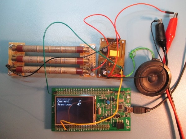
This article describes a high-sensitivity Geiger–Müller counter project utilizing three Soviet STS-5 lamps to detect low-level natural radiation. The device operates by applying high voltage (380–420V) to ionize gas within the tubes, generating pulses proportional to radiation levels. Key components include an MC34063 DC/DC converter for stable high voltage, resistors for current limiting and signal measurement, and comparator circuits to filter noise and drive LEDs or speakers.
Parts used in the Geiger–Müller Counter:
- Three Soviet STS-5 lamps
- MC34063 DC/DC converter
- Resistors R1 and R5 (1-10M range)
- Resistor R2 (10-220k range)
- Resistors R3 and R4
- Capacitor C3
- IC1A comparator circuit
- Resistors R7 and R8
- Resistors R9, R10, and R11
- Transistors
- LED and speaker
The Geiger–Müller counter is a relatively simple tool to measure ionizing radiation. To increase sensitivity, construction presented here contains three (instead of one as usually) soviet STS-5 lamps. This is important for measurements of natural sources of (low) radiation like soil, rocks (an article about my trip with Geiger–Müller counter on Śnieżka mountain).
Principle of operation of a Geiger–Müller counter
When high voltage (typically 380-420V) is applied to the Geiger–Müller tube, the tube doesn’t conducts electricity, but it does conducts for a short period, when radiation particle is observed. Those pulses are observed by the detector. The level of ionizing radiation is proportional to the amount of pulses detected in a constant interval of time (typically from 20s to 2,5min).
Geiger–Müller tube behavior can be described as a “button”, that is “pushed” by an ionizing particle.
Let’s go further into the details. Geiger–Müller tube is made of two electrodes, ionizing particle creates a spark gap between them, to reduce amount of current that flows in this situation, a resistor is put in series with the tube. Marked as R1 on above circuit, R5 on below. Typically it’s in a range 1-10M, acceptable values are listed in documentation of the GM tube.
There are a different ways to obtain a signal from the tube, in presented here, a resistor is connected in series between the tube and ground, changes of the voltage on the resistor are measured by the detector. This resistor is marked as R2 on above diagram, R6 on below. Typically it’s in a range 10-220k.
Similarly to diode, a Geiger–Müller tube has its polarity, when connected in the opposite direction it will work incorrectly.
Below is shown a signal from GM tube when a particle is detected. Periodic spikes are from HV supply (DC/DC converter).
The electronic circuit of a Geiger–Müller counter
MC34063 is a DC/DC converter used to produce required high voltage, one of it’s advantage over a simple NE555 or similar generators in this circuit is that it can monitor the output voltage and adjusts parameters to make it stable (R3, R4, C3).
IC1A, R7, R8 are used as a comparator to filter out noises and produce binary signal (low=no pulse at this moment, high=pulse is currently being observed). R9, R10, R11 and a bunch of transistors drives LED, a speaker and (as an option) external digital devices, e.g. Arduino, or other evaluation board.
For more detail: Geiger–Müller counter that can work with Arduino or (almost) any evaluation board
- How does the Geiger–Müller counter increase sensitivity?
The construction uses three Soviet STS-5 lamps instead of the usual single lamp. - What is the typical high voltage applied to the tube?
The typical voltage applied is between 380V and 420V. - How long is the interval for measuring pulse amounts?
The constant interval for measurement typically ranges from 20 seconds to 2.5 minutes. - What component is used to produce the required high voltage?
An MC34063 DC/DC converter is used to generate the necessary high voltage. - Does the Geiger–Müller tube have polarity?
Yes, the tube has polarity and will work incorrectly if connected in the opposite direction. - What is the function of resistor R1 in the circuit?
Resistor R1 is placed in series with the tube to reduce the amount of current flowing during a spark gap event. - How are signals filtered out as noise in this design?
IC1A, R7, and R8 are used as a comparator to filter out noises and produce a binary signal. - Can this device work with external evaluation boards?
Yes, it can connect to external digital devices like an Arduino or other evaluation boards.