Summary of Arduino Laser Show with Full XY Control using arduino
This project builds a DIY laser show using an Arduino, two speaker-based galvos (X and Y), and a laser pointer, allowing full X/Y beam control to draw text and simple images. It converts audio speakers into mirror-positioning galvos, uses TIP120 transistors and a 12V supply to drive them, and mounts small mirrors on speaker pivots. Estimated cost ~ $35 (excluding Arduino) and suitable for someone comfortable uploading Arduino code and soldering.
Parts used in the Arduino Laser Show Project:
- Arduino board (Atmega328 based, e.g., Duemilanove or Uno)
- Red pocket laser pointer (3 x 1.5V coin cell powered)
- 12V, 3A power supply
- 2 x 8-Ohm, 20-watt non-inductive resistors (or 2 x 6A, 50V rectifier diodes alternative)
- 2 x 100-Ohm resistors
- 2 x TIP120 Darlington transistors
- 2 x TO-220 heat sinks
- 2 x 470uF 35V radial electrolytic capacitors
- 2 x alligator clips
- 22 gauge solid core hookup wire
- 20 gauge or thicker hookup wire (speaker/power wire)
- 2 x 4 to 6 inch woofer speakers (galvos)
- C-clamps (variety)
- Spring clamp (for aiming)
- Optional: 18 x 24 plywood project board
- Coleman acrylic camping mirror
- 2 x #6 bolts and nuts
- 2 x wood skewers
- Scotch tape
- 4 x 2x4 Lego blocks (spacers)
- Soldering iron and solder
- Hot glue gun and hot glue
- Bandsaw, hacksaw, or rotary tool for cutting mirror
Update! See Step 32 to find out how to use this project with a green laser!
Also – checkout the LaserTweet Instructable to make this project display data from Twitter:
http://www.instructables.com/id/LaserTweet-Twitter-Projecting-Laser-Show/
This project uses an Arduino and some cheap audio speakers to create a real laser show with full X and Y axis control.
The included source code lets you easily draw text and even simple pictures!
You should be able to get most components locally (besides the Arduino).
Assuming you already have an Arduino – expect to spend roughly $35 on this project.
If you can upload a program to an Arduino and solder – you can probably build this project in an afternoon.
Users who have built this project:
mattbeowulf – http://www.youtube.com/watch?v=AnIoWZpEWk8
minhenes (using “real” galvos) – http://www.youtube.com/watch?v=BmYg3O4hlMg
hydronics – http://www.youtube.com/watch?v=5Q3nJLA2t18
http://www.instructables.com/id/Guerilla-Laser/
benhgd – http://www.youtube.com/watch?v=K23-ThlCZEc
(Post a comment with your link – and I’ll add yours to this list)
Step 1: A Bit About Laser Shows
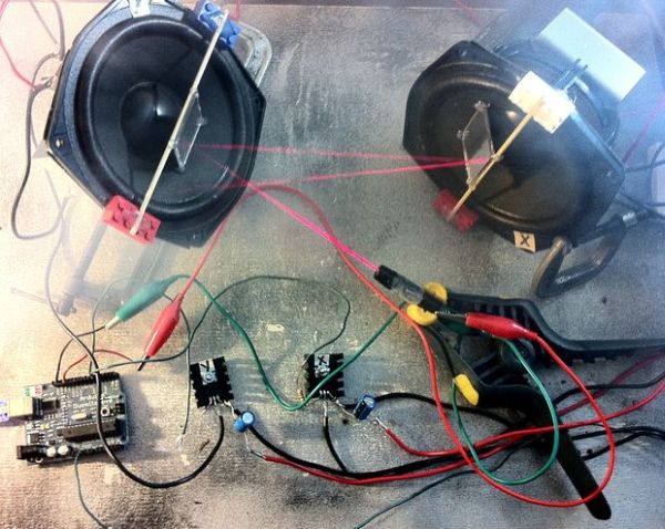
Most laser shows use galvonometers (the little boxes in the picture) or “galvos” to aim their mirrors.
Galvonometers are electromechanical devices that rotate to different angles based on how much voltage they are provided.
A minimum of two galvos are used – one for “X” (horizontal) control and one for “Y” (vertical control).
The laser show’s controlling electronics quickly adjusts galvo voltages, and turns the laser on and off – moving it around so quickly that it appears to create a persistent image.
Commercially available galvos can move to up to 50,000 different points each second.
Galvos tend to be expensive – so we’ll be making our own out of audio speakers!
Step 2: Stuff You’ll Need – Electronics
Arduino Board
This project has been tested on an Arduino Duemilanove (Atmega 328). Other 16MHZ Arduino boards with an Atmega 328 (such as the Uno) should work fine.
An Arduino with an Atmega 168 should work – but be aware the project barely fits into its memory – so you may hit issues adding your own functionality.
It’s assumed you have a programming cable, a computer with the Arduino environment installed, etc.
Red Pocket Laser Pointer
Look for one powered by three 1.5v coin cell batteries.
If you’re having trouble finding one at your favorite super store – check the pet toys section.
12v 3 Amp Power Supply
Voltage can be a bit higher or lower but needs to provide at least 3 amps of current.
You might find an old laptop power adapter at a thrift store with these specs.
Alternately – you can modify a PC ATX power supply.
Radio Shack Catalog # 22-507 would work fine – but is too expensive for what it is.
If you can’t find a usable power supply locally – you can get one on eBay for about $15.
2 x 8-Ohm, 20-watt Non-Inductive Resistors
Available at Radio Shack – Catalog # 271-120
(alternatively – 2 x 6A, 50V Rectifier Diodes Radio Shack #276-1661 – see step 17 for details)
2 x 100-Ohm Resistors
Doesn’t need to be exact value / wattage doesn’t matter.
Available at Radio Shack – Catalog # 271-1311
2 x TIP120 Darlington Transistors
Available at Radio Shack – Catalog #: 276-2068
2 x TO-220 Heat Sinks (for Transistors)
These are required! Without them the transistors will quickly overheat!
Available at Radio Shack – Catalog #: 276-1363
2 x 470uF 35V Radial-lead Electrolytic Capacitor
Available at Radio Shack – Catalog #: 272-1030
2 x Alligator Clips
These make connecting to the laser pointer’s battery leads easier.
Variety of options available at Radio Shack.
22 Gauge Solid Core Hookup Wire
This wire easily fits into Arduino headers. Not needed if you have a better solution.
Available at Radio Shack – Catalog # 278-1221
20 Gauge or Thicker Hookup Wire
For power connections – “speaker wire” should work fine.
Green Laser Parts (Optional)
If you plan on using a green laser – check out step 32 – there are few extra parts you’ll need.
Step 3: Stuff You’ll Need – Speakers
Two 4 to 6 inch “woofer” speakers
Speaker quality does make a difference in performance.
I’ve found speakers with large magnets and power ratings of 80 watts or more tend to work best.
Look for something that might be capable of producing some bass. You should be able to easily push the speaker cone in by about a 1/4″ if you press on it.
Using a speaker larger than 6″ will not necessarily help (and might hurt) performance.
The speakers do not have to match.
I extracted the pictured speakers from a set of 120 watt bookshelf-sized speakers I bought for $8 at a local thrift store.
They measure approximately 5 1/2″ across and are rated at 6ohm.
Advanced Technical Stuff Below (Optional Reading)
There are at least two technical variables that effect how well a speaker driver will work for the laser show.
Resonant Frequency: The frequency the speaker will vibrate at most easily on its own.
Qts or Q: This number describes how the speaker’s frequency response varies around the resonant frequency.
The pictured speakers had a resonant frequency of 63hz and a Qts of .55. They worked quite well.
I also had good luck with speakers having a resonant frequency of 81hz and a Qts of .96.
I have also tested a set of speakers with a resonant frequency of 120hz and Qts of 1.4 – which resulted in poor results.
My suggestion would be to look for a driver with a Qts between .5 and 1 with a resonant frequency between 50hz and 85hz.
Other speaker parameters (like Vas) may or may not effect project performance.
If purchasing speakers from a website like http://www.parts-express.com/ – you’ll be able to select from a wide variety of speakers that provide these specifications.
Look for close-outs / deals. As of last check, these drivers: http://www.parts-express.com/pe/showdetl.cfm?Partnumber=299-065 looked quite promising for only $5 each.
If you want to try testing your own speakers – take a look at this site: http://www.bcae1.com/spboxad3.htm
Step 4: Stuff You’ll Need – Mounting Hardware
This project requires positioning the laser and both “galvos” (speakers) so the laser bounces off the first galvo, onto the second galvo, then onto the wall.
While this isn’t a high-precision operation – it can be a little tricky.
The right tools for the job will depend on the exact size and shape of your speakers.
If you don’t already have the items below – look in your toolbox and junk drawer and improvise!
A Variety of C-clamps
4 clamps sized 2 1/2 to 4 inches should work for most speakers.
Spring Clamp
Used to point the laser.
Optional: 18″ x 24″ Plywood Project Board
This project has a fair number of pieces to it. Keeping everything on a project board can help keep it from getting out of control.
After you get everything working – you may want to replace the C-clamps with some kind of mounting solution that can be more permanently attached to the board (like brackets).
Step 5: Stuff You’ll Need – Tools and Misc.
Coleman Acrylic Camping Mirror
About $2.50 at your local sporting goods store.
2 x #6 Bolts and Nuts
For mounting heat sinks to transistors / length doesn’t matter.
2 x Wood Skewers
Like for cooking Shish Kabobs.
Scotch Tape
Or any kind of tape.
4 x 2×4 Lego Blocks
These are just used as spacers. You can substitute anything of similar shape / size.
Soldering Iron
And solder – gauge doesn’t matter.
Hot Glue Gun
And hot glue – attempt other adhesive techniques at your own risk.
Bandsaw or Hacksaw
Used to cut the acrylic mirror. A rotary tool with a cutoff wheel should also work.
Step 6: Cutting the Mirrors
Mark two 1.5 inch squares on the back of the acrylic camping mirror.
Cut out the mirror squares using a band saw, hacksaw or rotary tool.
If using a band saw – cut face-down with a paper towel between the saw table and mirror to prevent scratching.
Be careful not to peel off the mirror’s shiny backing.
Step 7: Install the Pivot Mounts
Use the hot glue gun to mount Lego blocks on opposite sides of one of the speakers as pictured.
The top of the Legos should be about 1/4″ above the foam surround of the speakers. If they are not – hot glue another object of appropriate thickness on top to achieve the needed height.
Step 8: Install the Mirror Pivot
Hot glue a wood skewer on top of the Legos – across the middle of the speaker.
The skewer will act as a pivot for the mirror.
After the glue cools, trim off the protruding end of the skewer with your cutting instrument of choice.
Step 9: Hot Glue the Mirror
Set one of the mirror squares on the speaker so it’s supported by the pivot on the left edge, and the speaker surface on its right edge.
Attach the mirror to the pivot and speaker using a small drop of hot glue at each of its corners.
Step 10: Make the Y Galvo and Label
Congratulations – you’ve finished the X galvo!
Now it’s time to make the Y galvo.
The Y galvo is exactly identical to the X galvo.
Repeat steps 7 through 9 to make it.
Label one galvo X and the other galvo Y using the method of your choice.
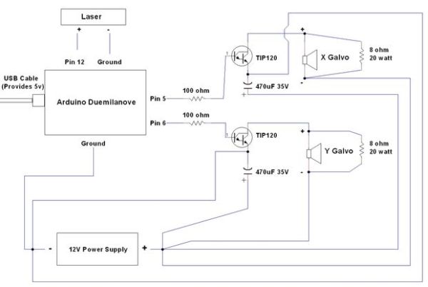
Step 11: Schematic
This schematic shows the electrical connections we’ll be making over the next several steps.
No need to memorize this – we’ll be going over every connection in detail!
(step 17 describes a minor variation on these plans – replacing the resistors with diodes for slightly improved efficiency)
Step 12: Tape Laser Pointer Into On Position
Wrap Scotch tape around the laser pointer’s button to force it into the on position.
Wrap it around tightly several times to assure it stays in place.
Step 13: Remove Laser Pointer End Cap
Remove the laser pointer’s end cap and batteries.
Examine inside – most laser pointers will have a spring that is the negative battery terminal.
Step 14: Connect Power Leads to Laser
Connect one alligator clip to the spring terminal (negative).
Connect the other alligator clip to the threading at the end of the case (positive).
Assure the clips don’t short each other.
Note: Some laser pointers may be constructed slightly differently – so adjust / improvise as needed.
Step 15: Connect Laser Power Leads to Arduino
The laser only draws about 25 milliamps at 5v – so it can be attached directly to the Arduino (good for 50ma)!
Connect the positive laser power lead to Pin 12 on your Arduino.
Cut a short piece of 22 gauge solid core wire and strip both ends.
Insert one end into Pin 12 on your Arduino board. Clip the alligator clip from the positive lead to the other.
Connect the negative laser power lead to a Ground Pin on your Arduino using the same method.
Step 16: Mount Heatsinks to Transistors and Label
Attach them tightly – it should be difficult to move the transistors.
The heat sinks must be installed . The transistors will quickly overheat otherwise.
Label one transistor X and the other transistor Y.
The transistors will act as switches – turning the small electrical signal the Arduino produces into a large electrical signal that can move the galvos.
Note: This part will get hot in normal use. Do not touch it when powered.
Step 17: Connect Resistors to Galvos
Connect the 8 ohm resistors across the positive and negative speaker leads of the X galvo using 20 gauge hookup wire and your soldering iron.
Use several inches of wire for these connections – so they won’t limit your ability to position the galvos later.
Repeat this step for the Y galvo.
Note: This part will get hot in normal use. Do not touch it when powered.
Note on Purpose of Resistors (optional reading)
As several users have noted – the purpose of the resistors seems to be to (inefficiently) eliminate back EMF generated by the speakers.
The resistors can alternately be replaced by diodes (such as http://www.radioshack.com/product/index.jsp?productId=2062591). This will result in somewhat decreased power consumption
The diodes should be connected so that the cathode (the side with the bar) is on the side of the speaker connecting to +12v.
This alteration may require tweaking the Arduino code to get good results (try increasing the x_min_value and y_min_value variables to about 20).
Step 18: Connect Galvos to Positive Power
Note: At this point your 12v power supply should be off / unplugged.
Connect the negative speaker terminal (indicated with a “-“) of the X galvo to the positive lead on your 12v power supply using 20 gauge hookup wire and your soldering iron.
Yes – to confirm — we’re connecting +12v to the negative speaker terminal .
Use ample wire for this connection (12 inches or more) – to assure you can position the galvos as needed later.
Repeat this step for the Y galvo.
Run a separate lead from each galvo back to the 12v power supply. Do not “chain” the connection between the two galvos.
For more detail: Arduino Laser Show with Full XY Control
- What does this project build?
A DIY laser show that uses an Arduino and two speaker-based galvos for full X/Y laser control. - Can I use regular speakers as galvos?
Yes; two 4 to 6 inch woofer speakers are converted into X and Y galvos by mounting small mirrors on pivots. - What Arduino is recommended?
An Arduino Duemilanove or other Atmega328 16MHz boards like the Uno; Atmega168 may have memory limits. - How is the laser powered and connected?
The laser pointer is taped on, batteries removed, and its positive lead connected to Arduino Pin 12 and negative to Arduino ground via alligator clips. - What powers the galvos?
A 12V, 3A power supply provides power to each speaker galvo, with separate leads for each galvo. - Are heat sinks necessary on the transistors?
Yes; TO-220 heat sinks must be installed on the TIP120 transistors to prevent rapid overheating. - What is the purpose of the 8-ohm resistors?
They are used across speaker leads to (inefficiently) eliminate back EMF; diodes can be used as an alternative. - Can I mount mirrors myself?
Yes; cut two 1.5 inch squares from an acrylic camping mirror and hot-glue them onto skewers mounted on Lego pivots on the speakers. - Do the speakers need matching specs?
No; speakers do not have to match, but those with large magnets and power ratings around 80W and resonant frequency 50–85Hz with Qts 0.5–1 work well. - How much will this cost?
Expect roughly $35 for components besides an Arduino, according to the article.