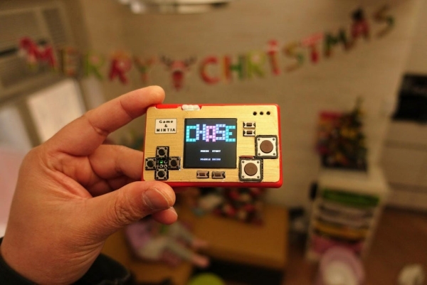
Summary of Game & MINTIA
Summary: This project fits an ESP32-based NES console into a MINTIA sweet box using a TTGO T7 v1.3, 1.54" ST7789 display, patched MAX98357 I2S DAC, thin prototype PCB, small speaker, Lipo battery, and tactile switches. It covers box preparation, component layout, hardware modifications, soldering, software setup with Arduino IDE, Arduino_GFX and arduino-nofrendo libraries, configuring pins and filesystem, and uploading firmware and ROMs to SPIFFS.
Parts used in the MINTIA NES Console:
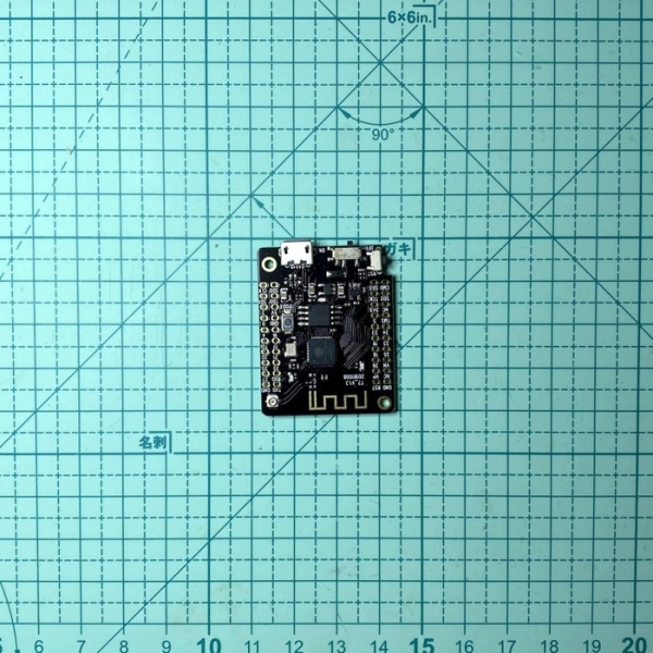
- TTGO T7 v1.3 (ESP32 dev board)
- 1.54" ST7789 IPS LCD
- Lipo battery 303040 (or 30 x 30 x 40 mm, ~360 mAh)
- MAX98357 I2S DAC audio breakout board (patched)
- 10 x 18 mm speaker
- Thin prototype PCB (≤ 1 mm)
- Four 6.2 x 6.2 x 5 mm tactile switches
- Two 12 x 12 x 4.3 mm tactile switches
- Four 6 x 3.5 x 5 mm tactile switches
- Hot glue (for fixing components)
- Soldering tools and wires
This instructables show how to use a tiny sweet box to make a NES console.
Supplies
TTGO T7 v1.3
https://www.aliexpress.com/af/Ttgo-t7-v1.3.html?d=…
1.54″ ST7789 IPS LCD
https://www.aliexpress.com/af/1.54-st7789.html?d=y…
Lipo 303040
https://www.aliexpress.com/af/lipo-303040.html?d=y…
MAX98357 I2S DAC audio breakout board
https://www.aliexpress.com/af/max98357.html?d=y&or…
10*18 mm speaker
https://www.aliexpress.com/af/1018-speaker.html?d=…
Thin Prototype PCB
https://www.aliexpress.com/af/lipo-303040.html?d=y…
Four 6.2*6.2*5 mm Tactile Switches
https://lcsc.com/product-detail/Tactile-Switches_D…
Two 12*12*4.3 mm Tactile Switches
https://lcsc.com/product-detail/Tactile-Switches_D…
Four 6*3.5*5 mm Tactile Switches
https://lcsc.com/product-detail/Tactile-Switches_D…
Step 1: What Is MINTIA?
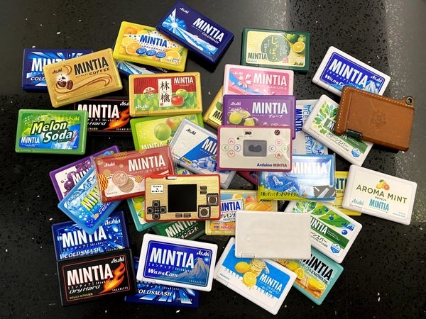
MINTIA is a multi favor tablet produced by Asahi Group Food, Ltd. in Japan since 1996. The sweet box design make it very easy to take one and only one tablet out when put off the cover, you can see the demo video how it works. MINTIA is very popular in Japan, it even have many 3rd parties tailor-made leather case for MINTIA.
The sweet box is very thin and the tablet outlet is very fit for the micro USB plug. MINTIA is over 20 years old, micro USB plug not yet born at that time! What a coincident!
4 years ago, I would like to squeeze all electronic components in it to find out how much it can be. This is the 3rd projects I built on MINTIA sweet box.
Asahi MINTIA page:
https://www.asahigroup-holdings.com/en/brand/minti…
MINTIA official Facebook page:
https://www.facebook.com/mintia.jp
My previous Mintia projects:
https://www.instructables.com/Arduino-MINTIA-Game-…
https://www.instructables.com/IoT-LED-Matrix/
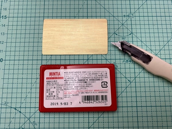
Step 2: Sweet Box Patch
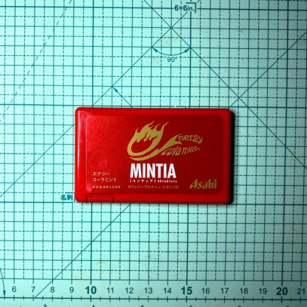
I would like to hide the NES console under the MINTIA sweet box, so I will keep the original front face unchanged. All magic hide at the back ;>
First of all I need consume all 50 MINTIA tablets. It is an easy job, I can consume box of it every week. Then remove the back face sticker. MINTIA box is well designed, front and back part assembled without glue. So it is very easy to tear apart after put off the tablet outlet cover. I would like to utilize all space in the box, so I will cut out all the internal supports.
Now I can squeeze all components inside it.
Step 3: Design Back Face Layout
I would like the NES console look like the Nintendo classic “Game & Watch” series. So I selected a red MINTIA sweet box. Then I use a gold color paper as a cover. Landscape layout, screen at the middle, direction buttons on the left, select and start buttons at the bottom and 2 big buttons on the right. Besides the standard NES buttons, I also require 2 more buttons for save and load status. So I add 2 more small buttons on the upper right.
Step 4: Hardware Selection
ESP32 Dev Board
This NES console is based on my previous instructables, Arduino NES, so it require a ESP32 dev board. Not much dev board can fit into the sweet box, TTGO T7 v1.3 is the small enough one after removed the Lipo Battery socket. The limitation is it does not have PSRAM, it limited the NES ROM can play.
Lipo Battery
The Lipo capacity direct limited the console playing life time, so it should be as big as possible. Exclude the room for the ESP32 dev board, there are still enough room for a 30 x 30 x 40 mm 360 mAH Lipo battery. I think it can last over an hour.
Display
1.54″ inches square display, ST7789 IPS LCD, is the largest display that can fit in MINTIA and still have enough room remain for the buttons.
Audio board
ESP32 can use internal DAC or external I2S DAC. Internal DAC still require an extra amplifier to drive a speaker and external have better sound quality, so I choose external I2S DAC amplifier board. No any I2S DAC audio breakout board can fit in the remaining room, so I need patch from a MAX98357 board.
Speaker
After MAX98357 patch, there are still have enough room can fit in a 10*18 mm speaker.
Prototype PCB
Normal PCB is too thick, we need a special thin (<= 1 mm) prototype PCB for holding the display and buttons.
Buttons
For better playing experience, this time I selected some light touch (125 gf / 160 gf operating force) tactile switches from Diptronics.
Step 5: Fix Dev Board & Lipo
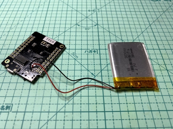
- Direct soldering Lipo to the original Lipo socket power pins
- Use hot glue fix the dev board on the sweet box and align the USB socket in the right place (beware hot glue should not touch any GPIO pins)
- Use a little bit hot glue fix the Lipo battery
- Double check the sweet box back cover can reassemble without problems
Step 6: I2S DAC Board Patch
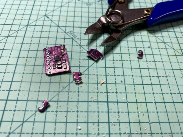
The MAX98357 board is a tiny square board but it still cannot fit in the sweet box. The upper part is the speaker connector and no any other electronic components. I will cut it out for saving space. The speaker still can connect by soldering the node between 2 capacitors as show in second photo. Then use hot glue fix in the sweet box and double check the sweet box back cover can reassemble without problems.
Then it is the soldering work, here are the connection summary:
ESP32        -> MAX98357
=====           ========
GPIO 15(TD0) -> LRC
GPIO 13(TCK) -> BCLK
GPIO 14(TMS) -> DIN
5V           -> Vin
GND          -> GND
             -> 100k Ohm resistor -> Gain (optional for 15 dB gain)
Ref.:
https://datasheets.maximintegrated.com/en/ds/MAX98…
Step 7: Early Test
After connected the first component, I2S DAC, I would like to check is it works. So switch to software part first.
Step 8: Software Preparation
Arduino IDE
Download and install Arduino IDE if you are not yet do it:
https://www.arduino.cc/en/main/software
ESP32 Support
Follow the Installation Instructions to add ESP32 support if you are not yet do it:
https://github.com/espressif/arduino-esp32
Arduino ESP32 filesystem uploader
Follow the installation steps to install Arduino ESP32 filesystem uploader if you are not yet do it:
https://github.com/me-no-dev/arduino-esp32fs-plugi…
Arduino_GFX Library
Download latest Arduino_GFX libraries: (press “Clone or Download” -> “Download ZIP”)
https://github.com/moononournation/Arduino_GFX
Import libraries in Arduino IDE. (Arduino IDE “Sketch” Menu -> “Include Library” -> “Add .ZIP Library” -> select downloaded ZIP file)
Arduino Nofrendo Library
Download latest Arduino Nofrendo libraries: (press “Clone or Download” -> “Download ZIP”)
https://github.com/moononournation/arduino-nofrend…
Import libraries in Arduino IDE. (Arduino IDE “Sketch” Menu -> “Include Library” -> “Add .ZIP Library” -> select downloaded ZIP file)
Step 9: Configuration
- Open esp32-nofrendo sample code in Arduino IDE (“File” -> “Example” -> “arduino-nofrendo” -> “esp32-nofrendo”)
- Save as a new project
- Change hardware parameters:
hwconfig.h around line 69, select SPIFFS
// Uncomment one of below, ESP32 support SPIFFS SD_MMC and SD
/* SPIFFS */
#define FILESYSTEM_BEGIN SPIFFS.begin(false, FSROOT); FS filesystem = SPIFFS;
/* 1-bit SD mode SD_MMC, always retry once for begin() failed */
// #define FILESYSTEM_BEGIN (!SD_MMC.begin(FSROOT, true)) && (!SD_MMC.begin(FSROOT, true)); FS filesystem = SD_MMC;
/* 4-bit SD mode SD_MMC, always retry once for begin() failed */
// #define FILESYSTEM_BEGIN (!SD_MMC.begin(FSROOT, false)) && (!SD_MMC.begin(FSROOT, false)); FS filesystem = SD_MMC;
/* SD using default SPI settings */
// #define FILESYSTEM_BEGIN SD.begin(22 /* SS */, SPI, 8000000, FSROOT); FS filesystem = SD;
/* SD using custom SPI settings */
// #define FILESYSTEM_BEGIN SPIClass spi = SPIClass(HSPI); spi.begin(14, 2, 15, 13); SD.begin(13, spi, 8000000, FSROOT); FS filesystem = SD;
hwconfig.h around line 81, set I2S DAC pins
// enable audio
#define HW_AUDIO
#define HW_AUDIO_EXTDAC
#define HW_AUDIO_EXTDAC_WCLK 15
#define HW_AUDIO_EXTDAC_BCLK 13
#define HW_AUDIO_EXTDAC_DOUT 14
#define HW_AUDIO_SAMPLERATE 22050
hwconfig.h around line 89, setting controller GPIO
/* controller is GPIO */
#define HW_CONTROLLER_GPIO
// #define HW_CONTROLLER_GPIO_ANALOG_JOYSTICK
// #define HW_CONTROLLER_GPIO_REVERSE_UD
// #define HW_CONTROLLER_GPIO_UP_DOWN 34
// #define HW_CONTROLLER_GPIO_REVERSE_LF
// #define HW_CONTROLLER_GPIO_LEFT_RIGHT 35
#define HW_CONTROLLER_GPIO_UP 12
#define HW_CONTROLLER_GPIO_DOWN 32
#define HW_CONTROLLER_GPIO_LEFT 25
#define HW_CONTROLLER_GPIO_RIGHT 27
#define HW_CONTROLLER_GPIO_SELECT 4
#define HW_CONTROLLER_GPIO_START 0
#define HW_CONTROLLER_GPIO_A 22
#define HW_CONTROLLER_GPIO_B 21
#define HW_CONTROLLER_GPIO_X 17
#define HW_CONTROLLER_GPIO_Y 16<br>
if your display is 9-bit SPI LCD, display.h around line 37
// #define TFT_BRIGHTNESS 128 /* 0 - 255 */

// #define TFT_BL 14
Arduino_DataBus *bus = new Arduino_ESP32SPI(-1 /* DC */, 5 /* CS */, 18 /* SCK */, 23 /* MOSI */, -1 /* MISO */);
Arduino_ST7789 *gfx = new Arduino_ST7789(bus, 33 /* RST */, 0 /* rotation */, true /* IPS */, 240 /* width */, 240 /* height */, 0 /* col offset 1 */, 80 /* row offset 1 */);

/* ST7796 on breadboard */
// #define TFT_BL 32
// Arduino_DataBus *bus = new Arduino_ESP32SPI_DMA(32 /* DC */, -1 /* CS */, 25 /* SCK */, 33 /* MOSI */, -1 /* MISO */);
// Arduino_TFT *gfx = new Arduino_ST7796(bus, -1 /* RST */, 1 /* rotation */);

/* ST7796 on LCDKit */
// #define TFT_BL 23
// Arduino_ESP32SPI_DMA *bus = new Arduino_ESP32SPI_DMA(19 /* DC */, 5 /* CS */, 22 /* SCK */, 21 /* MOSI */, -1 /* MISO */);
// Arduino_ST7796 *gfx = new Arduino_ST7796(bus, 18, 1 /* rotation */);
if your display is normal SPI LCD, display.h around line 37
// #define TFT_BRIGHTNESS 128 /* 0 - 255 */

// #define TFT_BL 14
Arduino_ESP32SPI_DMA *bus = new Arduino_ESP32SPI_DMA(14 /* DC */, 5 /* CS */, 18 /* SCK */, 23 /* MOSI */, -1 /* MISO */);
Arduino_ST7789 *gfx = new Arduino_ST7789(bus, 33 /* RST */, 0 /* rotation */, true /* IPS */, 240 /* width */, 240 /* height */, 0 /* col offset 1 */, 80 /* row offset 1 */);

/* ST7796 on breadboard */
// #define TFT_BL 32
// Arduino_DataBus *bus = new Arduino_ESP32SPI_DMA(32 /* DC */, -1 /* CS */, 25 /* SCK */, 33 /* MOSI */, -1 /* MISO */);
// Arduino_TFT *gfx = new Arduino_ST7796(bus, -1 /* RST */, 1 /* rotation */);

/* ST7796 on LCDKit */
// #define TFT_BL 23
// Arduino_ESP32SPI_DMA *bus = new Arduino_ESP32SPI_DMA(19 /* DC */, 5 /* CS */, 22 /* SCK */, 21 /* MOSI */, -1 /* MISO */);
// Arduino_ST7796 *gfx = new Arduino_ST7796(bus, 18, 1 /* rotation */);
Step 10: Program
- Connect the device with USB cable
- Open Arduino IDE
- Open esp32-nofrendo sample code (“File” -> “Example” -> “arduino-nofrendo” -> “esp32-nofrendo”)
- Press Arduino IDE “Upload” button
- Select “Tools” menu in Arduino IDE -> “ESP32 Sketch Data Upload” will upload the ROM file to ESP32 SPIFFS.
Source: Game & MINTIA
- What dev board is used for the NES console?
TTGO T7 v1.3 ESP32 dev board is used because it fits inside the MINTIA box after removing the Lipo socket. - What display fits in the MINTIA box?
A 1.54 inch ST7789 IPS LCD is the largest display that fits while leaving room for buttons. - Which audio solution is chosen?
An external MAX98357 I2S DAC breakout board is used for better sound quality and to drive the speaker. - How is the MAX98357 board modified to fit?
The speaker connector section is cut off and the speaker is soldered to the node between two capacitors; the board is then glued into the box. - What filesystem is configured for storing ROMs?
SPIFFS is selected in hwconfig.h for the ESP32 filesystem. - Which GPIO pins are set for the I2S DAC?
GPIO 15 for WCLK (LRC), GPIO 13 for BCLK, and GPIO 14 for DIN, with 5V to Vin and GND to GND. - How are controller buttons mapped?
Controller GPIO pins are defined in hwconfig.h, for example UP 12, DOWN 32, LEFT 25, RIGHT 27, SELECT 4, START 0, A 22, B 21, X 17, Y 16. - What software libraries are required?
Arduino_GFX and arduino-nofrendo libraries are required, and ESP32 support plus the Arduino ESP32 filesystem uploader in Arduino IDE. - How do you upload the program and ROMs?
Upload the sketch via Arduino IDE Upload button and use ESP32 Sketch Data Upload to send ROM files to SPIFFS. - How is the hardware fixed inside the box?
The dev board and battery are secured with hot glue and the Lipo is soldered to original power pins; ensure the back cover still reassembles.