Summary of Freeform Arduino
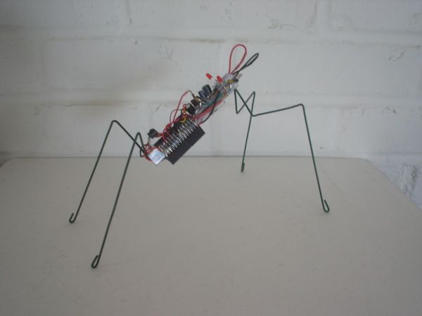
The "Freeform Arduino" is an experimental project where the artist uses electronic components instead of traditional art materials to create without planning or sketches. The goal is to let instinct guide the assembly, disregarding the final outcome. The build involves soldering a minimal circuit using an ATmega microcontroller and power regulators, then housing the entire assembly inside a repurposed antistatic tube.
Parts used in the Freeform Arduino:
- ATmega168/328 preloaded with Arduino Bootloader
- 16 Mhz Resonator
- 10K Resistor (Radio Shack #271-1335)
- 0.1uF Capacitors (Radio Shack #272-135)
- 3mm red LED (Radio Shack #276-026)
- 1K Resistor (Radio Shack #271-1321)
- 6-pin Male Header
- 100uF Capacitor (Radio Shack #272-1025)
- 10uF Capacitor
- +5V Voltage Regulator
- +3V3 Voltage Regulator
- Diode 1N4001
- Antistatic Tube
As an artist, sometime I created an art pieces without planning ahead what I want to draw or paint, just want to add colors or lines onto the drawing or canvas, and never think of the outcome of the piece. Let’s our own instinct and subconscious leading away!
Then I thought, “What if I am using electronic components, solder iron, and such, as my materials instead of the paint brush, pen, to create a project without planning ahead, and not to worry about the outcome that the project, no sketch of how it would look like, and do not care whether it would be success or failure?”
And the “Freeform Arduino” was the result of the conviction.
Step 1: Parts & Tools
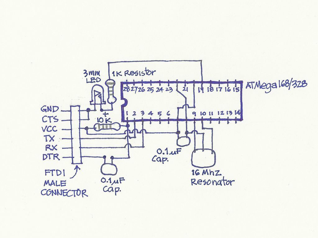
Schematic shown below is comprised of the minimum components and could be used FTDI cable to upload the sketch and has the LED connected to pin D13.
Parts
Parts are not certain at this point, and will added as I thing would be suitable at the time.
For now it would be at least,
ATmega168/328 preloaded with Arduino Bootloader,
16 Mhz Resonator,
10K Resistor (Radio Shack #271-1335)
0.1uF Capacitors (Radio Shack #272-135)
3mm red LED(Radio Shack #276-026)
1K Resistor (Radio Shack #271-1321)
6-pin Male Header (as the connector to FTDI cable to upload the sketch)
This are the minimum components to get Arduino up and running.
Tools
The tools that I used in this project are:
Solder iron and Solder station
Hookup Wire
Diagonal Cutter
Pliers
X-Acto Knife
Wire Stripper
SolderSucker
Step 2: Power Supplies
I took an ATMega168-20PU out of my old Arduino board which I haven’t used anymore. The board still function properly, and it would be safer to try out with old ATmega168 chip instead of using the newer version, i.e ATmega328P.
My first thought on this project was about the power supply to the Microcontroller. So I started with the 5V regulator.
And continue on to 3.3V regulator. By soldered the components without using the PCB.
5V and 3.3V Power Supplies
Here are the part lists of the 5V and 3.3V regulators:
0.1uF Capacitors (Radio Shack #272-135)
100uF Capacitor (Radio Shack #272-1025)
10uF Capacitor
+5V Voltage Regulator (Radio Shack #276-1770) or (DigiKey #LM78L05CZFS-ND)
+3V3 Voltage Regulator (DigiKey #MCP1700-3302E/TO-ND)
Diode 1N4001 (Radio Shack #276-1101)
Step 3: Antistatic Tube As A Case?
What would be the suitable container or case for the project?
I went through my component box and found the antistatic tubes.
I thought “Will this work?” Looking at it carefully, “Let’s see!”
I started to draw the lines on the tube itself. And And thought that the power supplies that I made earlier is about the same size of the tube.
Also, I thought to place the microcontroller ATMega168 linear to the power supplies that I did earlier.
Then I cut the top side of the tube to have enought room for both power supply and microcontroller.
Then, I got the idea to put the FTDI connector (6-pin male header) at the end of the tube.
So I cut two notch at the end of the tube. (seen in the last three images below).
16 Mhz Resonator,
10K Resistor (Radio Shack #271-1335)
0.1uF Capacitors (Radio Shack #272-135)
3mm red LED(Radio Shack #276-026)
1K Resistor (Radio Shack #271-1321)
6-pin Male Header (as the connector to FTDI cable to upload the sketch)
This are the minimum components to get Arduino up and running.
For more detail: Freeform Arduino
- What inspired the creation of the Freeform Arduino?
The artist wanted to use electronic components like solder irons instead of paint brushes to create projects without planning or worrying about the outcome. - Can I use a newer ATmega328P chip for this project?
The author chose to use an old ATmega168 chip because it was safer to try out than the newer version. - Does the schematic require a PCB board?
No, the author soldered the components without using a PCB board. - How did the author decide on the case for the project?
The author found an antistatic tube in their component box and decided to cut it to fit the microcontroller and power supplies. - What tool is used to upload the sketch to the board?
An FTDI cable connected to a 6-pin male header is used to upload the sketch. - Which specific resistor values are listed for the minimum components?
The list includes a 10K Resistor and a 1K Resistor. - Are the power supply voltages fixed at only one level?
No, the project includes both a 5V regulator and a 3.3V regulator. - What happens if the project fails according to the article?
The creator does not care whether the project will be a success or failure.