So have you heard of sous vide? Well, this Lazy Old Geek (LOG) hasn’t or hadn’t.
http://en.wikipedia.org/wiki/Sous-vide
It’s French. So it’s kind of like boil-in-a-bag only you don’t boil it.
The equipment can be rather expensive.
http://www.sousvidesupreme.com/Shop_Online/SousVide_Supreme_Demi/Department.aspx?DeptID=3&&AdID=245&gclid=CN7PyM6uw7cCFWNp7AodomkA6g
I thought that was rather expensive for a tender steak, so I decided to make my own.
There are a lot of other Instructables on doing this:
http://www.instructables.com/id/Make-your-own-programmable-thermostat-with-Arduino/?download=pdf#intro
http://www.instructables.com/id/Sous-Vide-temperature-controller-for-50-100/?ALLSTEPS
http://www.instructables.com/id/Sous-vide-cooker-for-less-than-40/
http://www.instructables.com/id/Arduino-Sous-Vide-Cooker/
*******************************************************************************************************************************
WARNING: Do not attempt to make this project unless you are familiar with working with 120 VAC. There is a shock hazard and fire hazard if you don’t know what you’re doing.
*******************************************************************************************************************************
WARNING: Be ware of pathogens. Sous vide techniques may not take care of pathogens if you don’t follow correct techniques.
Quoting Douglas Baldwin:
“Raw food often has millions of microorganisms on or in it; most of these microorganisms are spoilage or beneficial bacteria and won’t make you sick. But some of these microorganisms are pathogens that can make you sick if you eat too many of them. Most food pathogens are bacteria, but some are viruses, funguses, and parasites. Your yogurt, aged cheese, and cured salami can have hundreds of millions of spoilage or beneficial bacteria in every serving; but they don’t make you sick because spoilage and beneficial bacteria are distinct from pathogens. Since pathogens don’t spoil food, you can’t see, smell, or taste them.”
http://www.douglasbaldwin.com/sous-vide.html
****************************************************************************************************************************************
By the way, this is a great introduction to sous vide. For sous vide novices, I highly recommend looking at ths:
http://www.douglasbaldwin.com/sous-vide.html
There’s a lot of technical information that you may want to skim over.
Step 1: Design
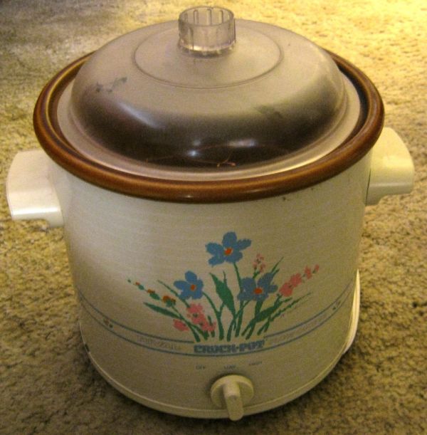
As others have done, my design uses a simple crock pot as the heating element. It has to be simple as the temperature is controlled by controlling the AC going to it.
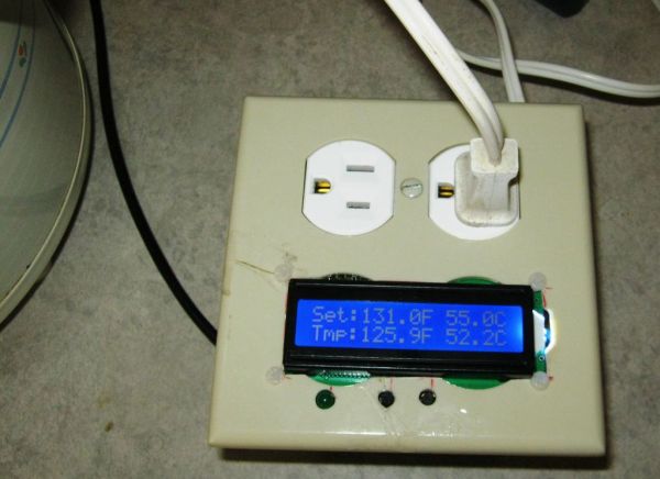
The controller is my own design Arduino using an LCD1602 for display and a Solid State Relay, SSR25DA to control AC for the crock pot.I also use a cheap USB power supply to provide 5Vdc for the Arduino. (see pictures)
Basic Theory: A temperature sensor is connected to the Arduino. The temperature sensor is placed in the crock pot submersed in water along with the food to be cooked. Two pushbuttons on the Arduino set the desired temperature. If the water temperature is below the set temperature, the SSR is turned on so AC is supplied to the crock pot and the water heats up. When the water temperature reaches the set temperature, the SSR turns off and the crock pot stops heating. Thus the water temperature stays at the set temperature.
Parts List
1 Crock Pot Simple design, on-off or high-low-off
1 Double AC box
1 Double AC cover
1 AC Outlet
1 SSR25DA Solid State Relay (see picture)
1 DS18B20 waterproof temperature probe
1 USB power supply (see picture)
1 L.O.G. souse vide PCB
1 ATmega328 microcontroller
1 LCD1602 display
1 16MHz crystal oscillator
2 22pF capacitors
1 47uFd 25V capacitor
1 0.01uFd capacitor
1 LED, 5mm
2 10K resistor
1 4.7K resistor
1 1K resistor
(2 KF301 connectors) not used
2 pushbutton tactile switch (tall)
I purchased most everything off of ebay and at my local hardware store. The crock pot is borrowed.
Step 2: DS18B20 Temperature probe
So you may ask, why did I select the DS18B20 for the temperature probe? There are many devices that are a lot cheaper.
The main reason is because they’re pre-calibrated. They are accurate to within ½ a degree C.
On ebay, the DS18B20 comes in two types: one is the TO-92 three lead package. The second is the waterproof type shown in the picture.
I have some of the TO-92 types and was thinking about making my own waterproof submersible one but I was feeling Lazy so I bought the waterproof version.
http://www.ebay.com/itm/M3AO-1pcs-DS18b20-Waterproof-Temperature-Sensors-Thermistor-Temperature-Control-/281127240637?pt=LH_DefaultDomain_0&hash=item41747d43bd
Here’s the datasheet
http://datasheets.maximintegrated.com/en/ds/DS18B20.pdf
The primary reason I selected the DS18B20 is the accuracy. It is calibrated to +/- 0.5C. Most of the other cheap temperature sensors have to (or should be) calibrated at various temperature points to achieve better accuracy.
Irrelevant Information: Calibration: A typical two point calibration is to use freezing temperature of water, 32F (0C)and boiling point of water, 212F (100C). But wait! This boiling point is only true at sea level. My altitude is about 4600 ft. so boiling water is about 203F. Okay, this is a lot of work and I’m LAZY so I will just assume that the DS18B20 is as accurate as claimed.
Secondary reason: the DS18B20 is digital as opposed to analog. Analog sensor accuracy varies with associated components and noise. Digital data is not subject to any of that.
Technobabble: The DS18B20 data is transferred serially, specifically SPI (Serial Peripheral Interface). But serial is digital. Simply speaking, there are two versions of digital data, serial and parallel.
Third reason: This one only a Geek can love. The DS18B20 uses something called a 1-wire buss. In theory what this means is that you only need one wire to connect the DS18B20 to the receiver (Arduino, in this case). In practice you need two wires as the circuit needs a ground. And full disclosure, I’m using three.
DS18B20 and the Arduino: So, of course the Arduino needs a special library for the DS18B20 or actually for the One wire. I think there may be variants on this library or at least different versions but I used this one:
http://www.pjrc.com/teensy/td_libs_OneWire.html
Here’s some more info on DS18B20:
http://arduino-info.wikispaces.com/Brick-Temperature-DS18B20
I am also using the Dallas Temperature library. I think the only thing I’m using it for is the conversion of Centigrade to Fahrenheit, which I could’ve written myself. However, there’s a lot of other things you can do with this library.
http://milesburton.com/Main_Page?title=Dallas_Temperature_Control_Library
*********************************************************************************************************************************
WARNING: Some of these waterproof DS18B20 ebay listings show the color code of the wires. Mine did but the code was wrong. Since I had a TO92 version, I used an ohmmeter to compare. Red was 5V, Green was signal and Yellow was ground. You may have different results.
**********************************************************************************************************************************
Step 3: L.O.G. sous vide PCB
Instead of using a standard Arduino and shield, I decided to build my own Arduino on a PCB.
There is a USB_BUB type connector like the one on a RBBB.
There’s places for connectors for 5Vdc, SSR and DS18B20 temperatrue probe.
This is a single sided PCB, so it’s easier for the DIYer to make. Because of this plus some space considerations, there are some unique problems. The Eagle Cadsoft schematic and PCB files are included.
The LCD1602 is attached to the back of this PCB.
1. The jumpers and all components except the pushbuttons and LED are soldered onto the component side.
2. The wires for the 5V-Gnd, SSR and DS18B20 come out the component side and are soldered to the solder side.
3. The pushbuttons and LED are inserted on the solder side. The LED is not inserted flush so that it sticks out and is easier to solder.
4. Male header pins are put in the solder side of the PCB and carefully soldered.
5. The LCD1602 is inserted onto the header pins and soldered.
(see pictures)
The schematic is attached. U$2 is for 5V in from USB power supply. The 10K potentiometer adjusts contrast on the LCD1602. The SSR connector goes to the SSR25DA (polarity is important) The DSx connections go to the DS18B20 temperature sensor.
I’ve included the Eagle Cadsoft files if you want to make your own PCB.
Step 4: DS18B20 Temperature Sensor
DS18B20 Address
Each DS18B20 sensor has a unique address. You need to know that address so that you can talk to it.
I would recommend that you test each DS18B20 on a breadboard and get its address before hand.
If you haven’t done this or can’t remember, here’s a way to find it after it’s already installed on one of these PCBs.
Connect the sous vide PCB to your PC with a USB adapter. I use a PL2303 module but you can also use a USB-BUB.
In the Arduino environment, make sure the correct serial port is selected. Under Board, select Arduino UNO.
Under ‘File’ ‘Examples’ scroll down to OneWire and select
DS18x20_Temperature
In the sketch about eight lines down, you will see this
OneWire ds(10); // on pin 10 (a 4.7K resistor is necessary)
10 is the Digital pin used in the example. Change it to:
OneWire ds(2); // on pin 10 (a 4.7K resistor is necessary)
Upload the program to the Arduino.
Open your Serial Monitor and set for 9600 baud. You should see something like the picture.
The first line shows the address: 28 6B 88 B4 4 0 0 D1
FYI, this is in hexadecimal. Write it down or put it in a database. This needs to go into the sous vide sketch. (The second line identifies the sensor and the fourth shows the temperature)
When you exit the environment, you don’t need to save the changes.
For more detail: L.O.G. sous vide