First of all, Happy New Year 2017! I hope all of yours starts the new year with good intentions. The mine one is write frequently here. Family and work don’t let me much free time but I’ll try it!
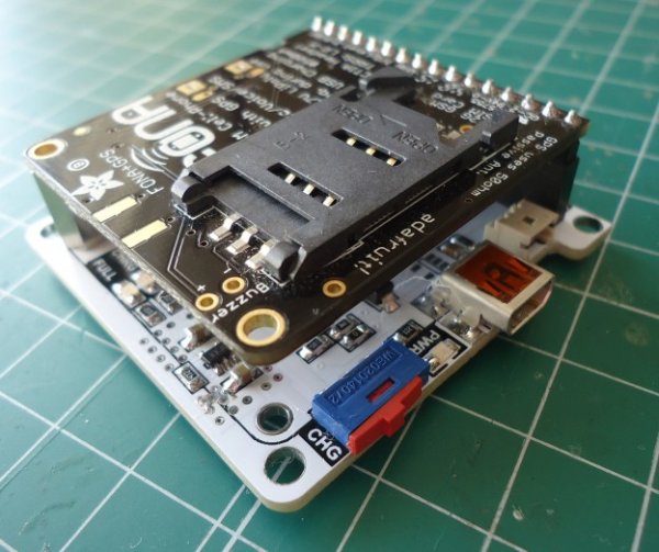
For several months I’m working with FONA808 modules from Adafruit to make a portable, web-based locating system. This modules are based on the SIM808 module from SIMCOM manufacturer, and integrates both GSM and GPS transceivers in one 24x24mm package. The Adafruit board includes this module and also some electronics for choosing voltage levels, battery connection and charger. Because I need to test and programming some of this modules, I decide to make an specific PCB for it, allowing the programming and debugging via PC, which is more comfortable that use a microcontroller for all these tasks. I use the MCP2221 USB-Serial bridge and add some electronics to give the board more functionality. So it has a connection for a 3.7Li-Ion battery, battery charger, manual pushbutton to turn on/off the module and also several leds to indicate the status of the different elements and network connections. So, let’s go for it!
- HARDWARE
As always, the first is the schematic of the board, you can find here: FONA808 PC Interface_V01. The board is based on the FONA808 module, so is designed around it. Here are the info about this module, it’s recommendable to read it if you don’t know this module.
- USB connection: I use the same Mini USB Molex connector of the previous boards, because it’s easy to solder by hand. With the USB connector you can communicate with the FONA808 module and also charging the battery.
- Local Battery: The FONA808 has it own battery connector and on-board charger, but I decide to add a second battery connector and charger. Basically because I work with other kind of batteries (LP603450) and I’ve got some of it at home. The battery charger is the well known MCP73832T-2ACI/OT from Microchip. I set up it to charge the battery at 212mA (R19, 4K7), and has two led’s to indicate the state of the charge (orange is charging and green is charged). The voltage to charge the battery comes from the USB port. Between the battery charger and the battery, there’s a switch S1. This switch allows to charge the battery alone (position 1-2). This feature is important because in the FONA808 module, the battery is permanently connected to the circuit, so when you’re charging it, always there’re loss due the circuits connected. Also, because the MCP2221 has four general IO pins, I add a voltage divider (R3+R5) to try to measure the battery level with the MCP2221 utility (at this time I don’t test this feature).
Read more: FONA808 USB Interface