Summary of First Solo Experience with Arduino and Choosing a Simple Circuit with IR Remote and Sensor
Summary: I completed a solo Arduino project, switching from an IR remote idea to an ultrasonic distance/proximity sensor after library/code issues. Following tutorials, I wired the HC-SR04-like ultrasonic sensor to pins 9 and 10, read distances via the serial monitor, and added red and green LEDs (with 330 Ω resistors) on pins 2 and 3 and a buzzer. The LEDs and buzzer respond to a 10 cm threshold. The project improved my Arduino coding confidence and practical breadboarding skills.
Parts used in the Proximity Sensor Project:
- Arduino board (Uno or similar)
- Ultrasonic distance sensor (Trig and Echo pins)
- Red LED
- Green LED
- 330-ohm resistors (for LEDs)
- Buzzer (connected in series with red LED)
- Breadboard
- Jumper wires
- USB cable (for power and uploading code)
CHOOSING A DIRECTION
For this assignment, I embarked on my inaugural solo experience with Arduino. After facing some challenges during the in-class tutorial, I felt apprehensive about dealing with the breadboard once more. Consequently, I made an early decision to work on a simpler circuit. While exploring the components of the Arduino kit, the IR remote and sensor piqued my interest. After conducting some online research, I stumbled upon a circuit and code that appeared to be quite straightforward.
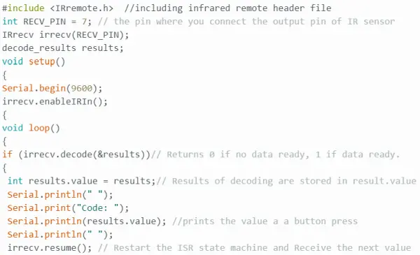
At the outset, I envisioned a setup where pressing a certain number on the remote would illuminate a specific combination of colored LEDs. To begin, I copied the provided code into the Arduino software for verification before proceeding with the actual circuit assembly. However, this required the installation and selection of an IRRemote library. Given multiple packages with the same name, I opted for the first one that appeared. After downloading the IR library, I attempted to verify the code but encountered an immediate error message.
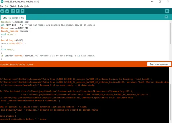
At this juncture, I encountered a recurring challenge throughout the assignment – my limited understanding of the coding language used in Arduino. The code provided was in C++, a language I hadn’t had the opportunity to learn previously. Having only experience with MATLAB, I found the syntax used for Arduino coding unfamiliar, making it difficult for me to interpret the error message.
To seek assistance, I approached one of my housemates, a Mechanical Engineer with Arduino experience. Unfortunately, he was unfamiliar with the IR remote/sensor library, so he couldn’t identify the issue either. Given the complexity and time-consuming nature of troubleshooting the IR remote code, I made the decision to opt for a simpler sensor system instead.
Switching Focus – Utilizing a Distance Sensor
In search of a new project idea, I turned to YouTube. Spending approximately an hour, I watched various videos like “Arduino for Beginners” and “Easy Arduino Projects.” I discovered that I found it much easier to learn through tutorial videos compared to reading instructions on the Arduino Project Hub posts. Among the common themes in beginner projects, the ultrasound sensor was frequently used for distance measurement.
Narrowing my focus, I delved into researching ultrasound sensor distance measuring circuits, watching a few tutorial videos. While some tutorials utilized a digital display to show the distance, I stumbled upon one video that demonstrated how to output this data to the serial monitor in the Arduino software.
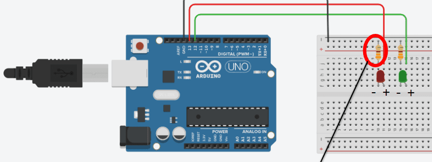
The video clarified that the ultrasound sensor emits an ultrasound wave at a specific frequency, and by measuring the travel time of the reflected wave, the distance can be calculated. This process involves configuring the pulse duration while considering the speed of sound, which is approximately 340 m/s. To set up the fundamental distance measuring circuit, I followed the wiring diagram provided in the video.
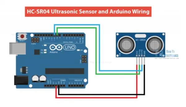
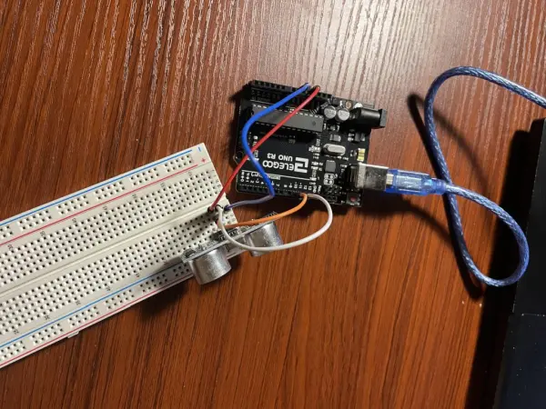
Having successfully set up the circuit, I proceeded to work on the coding part for the distance sensor. I made sure to connect the echo pin of the ultrasound sensor to the 10 pin on the Arduino board and the trig pin to the 9 pin, mindful of my previous mistake during the in-class tutorial where I had not specified the correct pins in the Arduino code. To prevent repeating that error, I took the time to comprehend the code provided in the video, rather than simply copy-pasting it as I did with the IR remote.
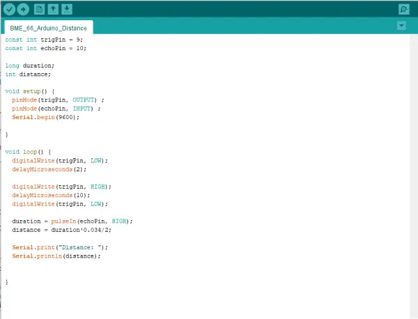
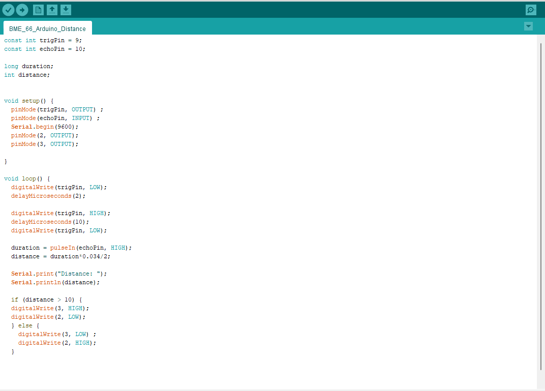
The code commences by assigning the Trig and Echo pins on the board as 9 and 10, respectively. In the setup section, the Trig pin is defined as an output, while the Echo pin is set as an input. To display the sensor readings on the serial monitor, the code incorporates the serial function. Moving on to the loop section, the state (low or high) and duration of the ultrasound waves are configured, along with the distance calculation. The resulting output is then sent to the serial monitor using the serial print function.
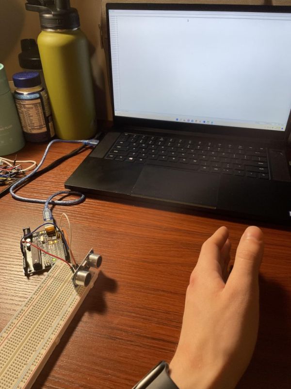
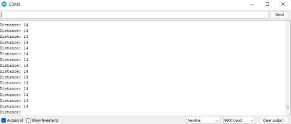
With the code successfully verified, I proceeded to upload it to my Arduino circuit. To check if the code worked correctly, I opened the serial monitor and placed my hand in front of the sensor. Fortunately, the serial monitor displayed the distance from my hand to the sensor in centimeters, confirming that it was functioning as intended.
Moving forward – Exploring the Proximity Sensor
To add my personal touch to the distance sensor circuit, I opted to incorporate the LED setup we learned during the in-class tutorial. My plan was to have a green light illuminate when an object is beyond a certain distance from the sensor, and a red light activate when the object is closer than that threshold. For this, I placed a red and green LED, each with a 330-ohm resistor, onto the breadboard. I connected the positive leg of each LED to digital pins 2 and 3 on the Arduino board.
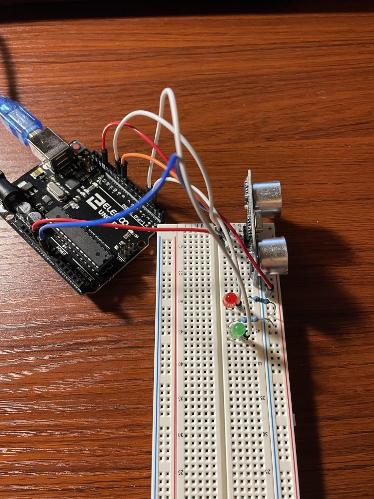
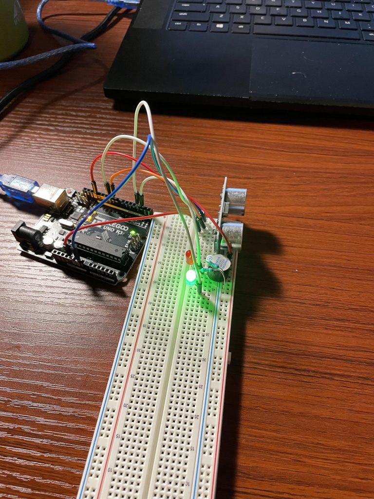
Now, my task was to develop the code that would illuminate the LEDs based on the readings from the distance sensor. Although the in-class example utilized temperature readings, I had to adapt that code for a different sensor. In the setup, I began by setting the pin modes of the LEDs to output. Next, I created an if loop that would set the green light output to high and the red light output to low when the distance reading exceeded 10 cm. Conversely, the else statement in the loop ensured the opposite would occur if an object came closer than 10 cm to the sensor. To add a dramatic effect, I connected a buzzer in series with the red light, so that when an object approached within 10 cm of the sensor, a sound would be emitted. With this, my proximity sensor was successfully assembled and programmed.
CONCLUDING THOUGHTS
Overall, this project turned out to be much more enjoyable than I initially anticipated. At first, I faced difficulties translating my vision for the proximity sensor into code, mainly due to my limited experience with the programming language. However, with persistence, trial and error, and seeking guidance from YouTube tutorials, I gradually improved my understanding of the syntax, which eventually led to the successful completion of my final product.
Another challenge I encountered was effectively managing the breadboard. Ensuring that all components were properly grounded and connected to the Arduino board proved to be tricky. Additionally, my fine motor skills were not the best, making it challenging to insert sensors and wires firmly into the board without feeling like I might break something. Nevertheless, I took extra care to double-check my connections before plugging the Arduino into my laptop to avoid any potential short-circuits.
In the end, overcoming these obstacles and witnessing my proximity sensor project come to life was immensely rewarding. The hands-on experience and problem-solving involved in this venture have boosted my confidence with Arduino and sparked my interest in further exploring and experimenting with electronics and coding projects.
Additionally, despite having attended a few classes on circuits, this assignment marked my first hands-on experience in actually constructing one. Working with diagrams can sometimes lead to overlooking critical aspects of circuit design, such as the significance of grounding. I quickly realized that both the LEDs and the ultrasound sensor needed proper grounding for the circuit to function correctly. This practical application provided me with valuable insights into circuit design.
Moreover, the assignment taught me the importance of adaptability during the design process. Initially, I had planned to work with the IR remote/sensor, as it seemed straightforward. However, when encountering code errors, I decided to pivot and instead made the LEDs responsive to the ultrasonic distance sensor. This flexibility allowed me to find a workable solution and achieve the desired outcome.
As a result of this experience, I feel more confident in using the Arduino for future projects, especially when prototyping for group endeavors. The hands-on learning and problem-solving involved in this assignment have sparked my interest in further exploring and applying Arduino-based solutions in various scenarios.
- What caused the project change from IR remote to ultrasonic sensor?
The IR project failed due to errors after installing an IRRemote library and unfamiliar C++ code, so the author chose a simpler ultrasonic sensor alternative. - How is the ultrasonic sensor connected to the Arduino?
The trig pin is connected to digital pin 9 and the echo pin to digital pin 10 on the Arduino. - How does the code calculate distance from the ultrasonic sensor?
The code measures pulse duration of the echo, uses the speed of sound, and computes distance, then prints it to the serial monitor. - What pins control the LEDs in the proximity setup?
The green LED is connected to digital pin 2 and the red LED to digital pin 3. - How does the project indicate proximity less than 10 cm?
If the measured distance is less than 10 cm the code sets the red LED high, the green LED low, and the buzzer sounds. - How was the buzzer integrated into the circuit?
The buzzer was connected in series with the red LED so it activates when the red LED is on. - How did the author verify the sensor was working?
After uploading the code, the author opened the serial monitor and confirmed it displayed the distance in centimeters when placing a hand in front of the sensor. - What grounding considerations were learned during the project?
The author learned that both the LEDs and the ultrasonic sensor require proper grounding for the circuit to function correctly.