Summary of Passive Sensors – Detecting Light and Motion
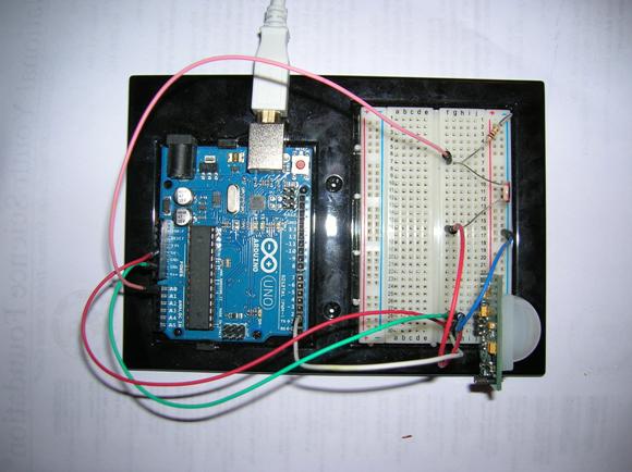
Summary: This project connects a CdS photosensitive resistor (PSR) and a Parallax PIR motion sensor to an Arduino UNO. The PSR and a 10K fixed resistor form a voltage divider whose midpoint is read on analog pin A0 to measure light. The PIR provides a digital motion signal to digital pin 2; its HIGH/LOW state drives the onboard LED on pin 13. The sketch initializes Serial at 9600 bps, configures pin modes, reads A0 and pin 2, prints the analog value, and updates the LED per the PIR input.
Parts used in the project:
- Arduino UNO microcomputer
- PC with Arduino IDE installed
- USB cable
- CdS PhotoSensitive Resistor (PSR)
- 10K Ohm fixed resistor
- Parallax PIR Motion Sensor
- Breadboard
- Jumper wires
- Onboard LED (Arduino pin 13)
Equipment: Arduino UNO microcomputer, PC with Arduino IDE installed, and a USB cable.
CdS PhotoSensitive Resistor(s), 10K Ohm Resistor, and Parallax PIR Motion Sensor
Passive sensors detect some physical phenomena and provide some amount of information about it that can be used for action or reaction. If sensors are passive, they may have an advantage over active sensors in some situations. Active sensors send out some kind of physical signal and read back some reaction to the signal from the environment. Passive sensors do not. However, the emission of a physical signal can be detected by an adversary such as an enemy in wartime. For example, RADAR can detect incoming enemy aircraft, ships, or vehicles, but it is active because it has to send out a radio signal to work. An enemy may use that radio signal as a homing beacon for a guided missile to destroy the RADAR antenna/installation. A passive system is less vulnerable and the enemy may not even know that it is there.
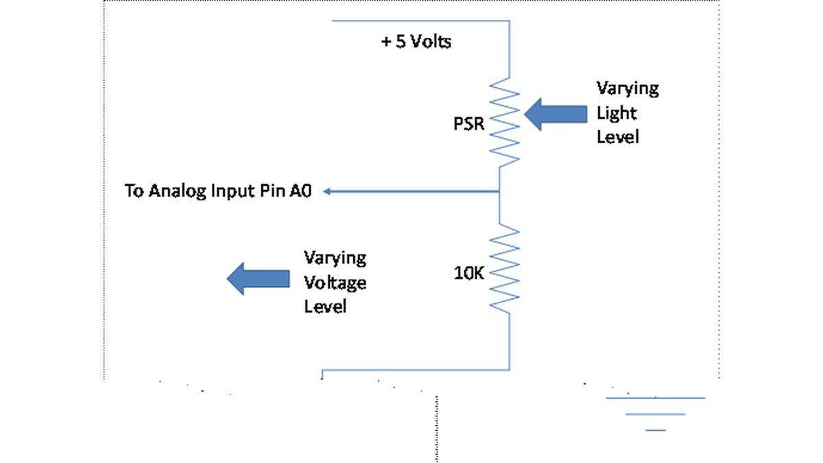
A photosensitive resistor (PSR) has a resistance value that depends on the amount of light striking its sensor surface. When you connect a PSR in series with a standard fixed resistor between a voltage source and ground, the amount of current flowing and hence the voltage across the fixed resistor will change with the level of light. This allows an Arduino program to detect the light level based on an analog input connected to the junction between the PSR and the fixed resistor.
The Parallax Passive Infrared Motion Sensor (PIR) allows an Arduino program to detect motion. Here is the data sheet for the Sensor: 555-28027-PIRSensor-v2.1.pdf. Please note that the SW shown is for a different microprocessor and IDE so you can only follow the general outlines and/or design of the code provided there.
Your assignment is to connect a PSR circuit and a PIR to the Arduino board. Disconnect the Arduino board from the USB port. Connect the appropriate devices and wires to the Arduino UNO via the breadboard. NOTE: When you are adding, changing, or removing wiring on a prototype connected to the Arduino UNO board, always disconnect the power from the USB port and check your wiring carefully before reconnecting it to the USB port. Otherwise, you may damage the Arduino board. If you have any doubts, show your wiring to the TA before reconnecting it to the USB port.
Select a 10K resistor and a PSR from the parts provided. Connect them in series between power and ground according to the following schematic diagram. Connect the junction between the two resistors to the Arduino analog input pin A0.
The PIR device requires +5V power and ground plus a signal line for one bit of data connected to digital pin 2 of the Arduino.
Connect the PC to the Arduino UNO board using the USB cable. Open the Arduino.exe program. Write the code for the sketch to read the analog input A0 value from the junction of the PSR and fixed resistor to display it on the monitor screen. Also, read digital input 2 as HIGH or LOW value from the PIR device and use that value to control the LED on the board via pin 13.
In the setup function for this sketch, you need to initialize the serial port for 9600 bps, setup the LED pin for OUTPUT, and setup the PIR pin for INPUT.
For more detail: Passive Sensors – Detecting Light and Motion
- How is the PSR connected to the Arduino?
The PSR is connected in series with a 10K resistor between +5V and ground, and the junction is connected to analog input A0. - Can the PIR sensor be read by the Arduino digitally?
Yes, the PIR sensor provides a digital signal line connected to digital pin 2 read as HIGH or LOW. - What pin controls the LED based on PIR input?
The onboard LED is controlled via pin 13 and is driven by the PIR input read on digital pin 2. - What serial speed should be initialized in setup?
The serial port should be initialized at 9600 bps in the setup function. - What pin modes need to be configured in setup?
Configure the LED pin as OUTPUT and the PIR pin as INPUT in setup. - How should wiring changes be handled when the Arduino is connected to USB?
You must disconnect the Arduino from the USB port before adding, changing, or removing wiring and verify wiring before reconnecting. - What does the analog reading at A0 represent?
The analog reading at A0 represents the voltage at the junction of the PSR and the 10K resistor, which varies with light level. - Does the PIR require a power connection?
Yes, the PIR requires +5V and ground plus the digital signal line to Arduino pin 2.