This is my first instructable post, and it is about the Home Automation shield for Arduino that I have created.
A little about myself my name is Krrish. I am 16 years old and currently in my senior year of high school.
I love making electronics projects and also love learning about tech. I decided to create this Arduino Shield as it is very useful and has practical applications.
Warning While Dealing With High Voltage Make Sure You Know What You Are Doing Otherwise It Could Be Fatal For You.
Supplies
1.Arduino Uno
2.Bc547 Transistors (4 pcs)
3.In4001 Diode (4pcs)
4.Home Automation Shield
5.Resistors
5.Led(Optional I have not used it)
6.5V Relays(4 Pcs)
7.Male and Female Header Pins
8.Screw Terminals
9.Soldering Iron
10.Soldering Wire
Step 1: Why This Shield
If you ever wanted to learn or make a Bluetooth home automation system using Arduino, you must have searched youtube about it. If you go through all the tutorials, they use Arduino and many wires to connect it to relay board, HC05 Module etc. That looks very untidy, and its practical application is also limited.
When I searched the internet, I couldn’t find any relay shield available for Arduino with Hc05 module pins.
So I decided to create the first-ever Bluetooth home automation shield for Arduino. It looks more professional, and it also can be used easily because the shield needs to be placed on the top of the Arduino Board, and we are done.
Here We Gooooo….
Step 2: Designing of Schematic Diagram
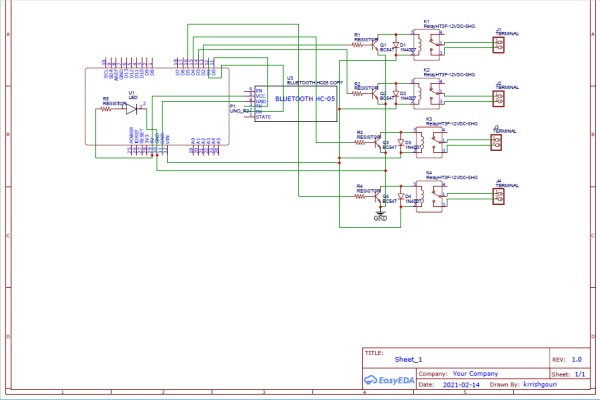
Designing or creating is a significant and crucial step as without it, we cant proceed further to make the Pcb Shield.
For designing the schematic Diagram, I used EasyEda software.
Of Course, there were many challenges, and it took time to fix them; as In the beginning, I was facing issues related to the size of components, but finally, I was able to get the result I wanted.
I am linking the pdf file for the schematic below.
Note: In Schematic Diagram and the Pcb shield, I have already connected the Tx of hc05 header pin to RX of Arduino and Rx of hc05 to tx of Ardunio. So you need to place or connect the Hc05 module directly
Lets move on further
Step 3: Converting the Schematic Design to Pcb
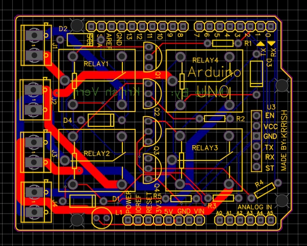
We are done with the schematic right now, so the PCB board layout must be created to turn the design into an actual PCB later on.
EasyEda has a feature to convert the schematic to the Pcb layout. I used that feature to create Pcb Design.
It was challenging for me initially as I was facing difficulty putting all the components in such a tight space, so I had to resize the board a bit. Change the positions of the components a million times to get things right.
The next channel was to route the track. I used the autoroute feature for that, but I also had to change things manually many times. You can either manually route or go with the autoroute function.
But finally, after sleepless nights, I managed to get everything together perfectly.
Well, I know you want to do this project. So I am linking the Gerber file for this project so you can order the PCB using that file
Here Is The Google Drive Link For Gerber File Gerber File
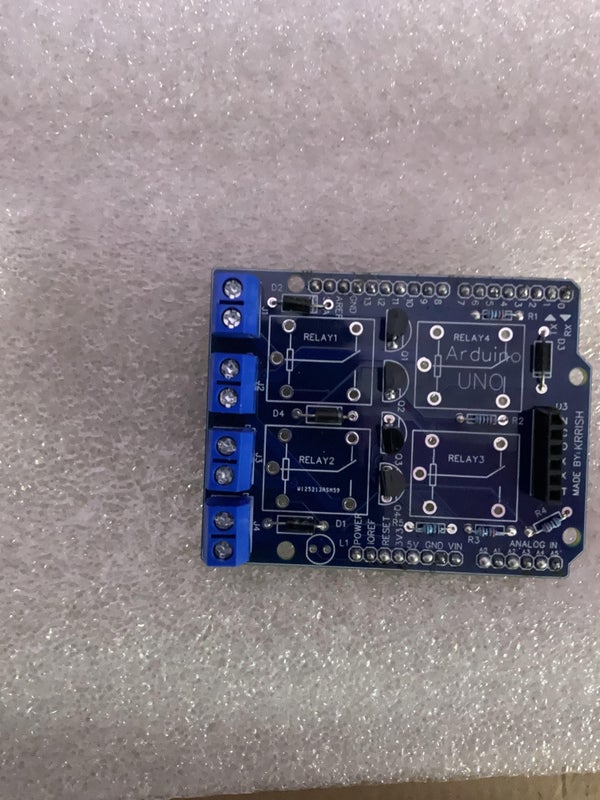
Step 4: Ordering the Pcb Board
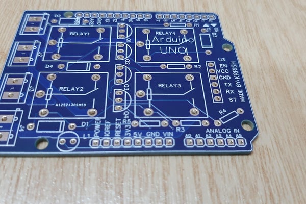
Now you just need to order the PCB board by uploading the Gerber file.
You can use any PCB manufacturing company like Jlcpcb, Pcbway etc
I personally used Pcbway for ordering my Pcb’s.
Now, let’s move further to the next step after you receive Pcb Boards.
Step 5: Soldering the Components According to the Schematics
We made schematics, Created a Pcb board and then ordered it by uploading the Gerber file.
Now comes the most important part of soldering all the components as, without it, our Pcb Shield will be useless.
Follow the schematic and labels on the Pcb Board to place all the components and solder them accordingly.
Now next step will be to place it on the Arduino board.
Step 6: Placing the Pcb Shield on the Arduino Board
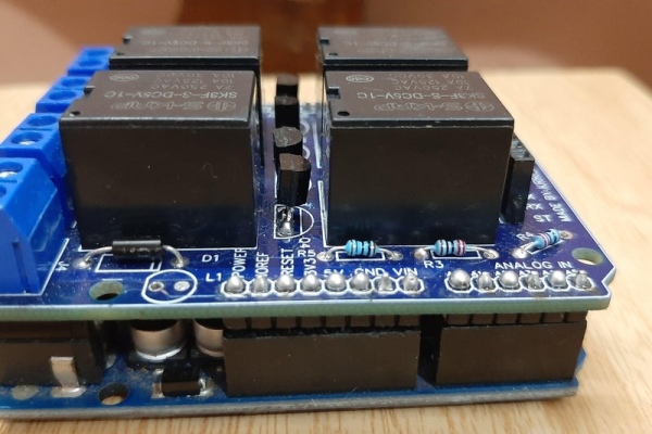
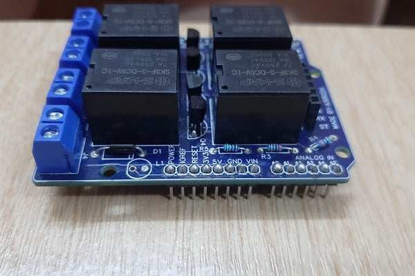
By This Time, Our Shield is completely ready to use, so now we need to place it on the Arduino with the help of male headers located on the shield so that all the connections get completed.
In The shield, there is a place to solder Led; it is completely optional. I have also not placed led as it is just for showing whether the board is receiving power or not
Step 7: The Coding Part
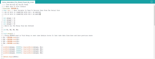
Until now, we have created the Shield, but we need to write a code that we will upload to the Arduino board so our shield can properly function.
This Code is written by me and also has an extraordinary feature,
The Code has EEPROM Function, which you will not find in youtube home automation videos.
EEPROM (electrically erasable programmable read-only memory) that can be erased or reprogrammed.
Suppose you create a simple home automation system without EEPROM. In that case, the practical use is minimal as in all the cases where EEPROM is not used whenever your Arduino board loses power, and when next time it gains power, it will reset, and all the devices will be turned off or on. But if we use Eeeprom, it stores the current state of each relay module, so if Arduino loses power and boots up next time, all the relays start in their previous states.
Just upload the sketch to the Arduino board, and you are good to move further to the next step
Step 8: Controlling the Relays Using Bluetooth
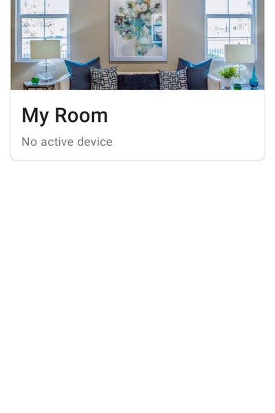
Now we have arrived to our last step of the whole process as now we need to control the relays using Bluetooth, so we need to set up the mobile application according to our needs.
For controlling the relays, you can use different apps
But my personal favorite are
1.Arduino Bluetooth Control By broxcode
You can use any of them, but the second one has a nice interface.
After installing, you have to edit buttons so you can set their value according to the code.
For example, To Turn relay one on, “A” has to be sent and to turn it off, “a” has to be sent. Similarly, you can set other buttons but make sure to follow the characters defined in the code for that.
Step 9: ThankYou and Congratulations
Thank you very much if you have come so far and were interested in my project. I hope you liked my project, and Congratulations to those who have completed the project.
Do let me know in the comments if you also made it or liked it or not, and feel free to ask any questions. I would love to answer them.
Source: First Ever Bluetooth Home Automation Shield for Arduino