Fast & Easy Fake-TV Light module built for under $5; with enhanced features. With the use of this device you can go for holidays or on vacation leaving your home with a lived in appearance and thus an added layer of security. “I’m up and I am a night owl … or perhaps asleep on the coach in front of the TV, ready to be awakened.”
My project was inspired by this Fake-TV project. I decided for my project to simplify the hardware involved, minimize assembly and make the software more sophisticated.
This instructable is the results.
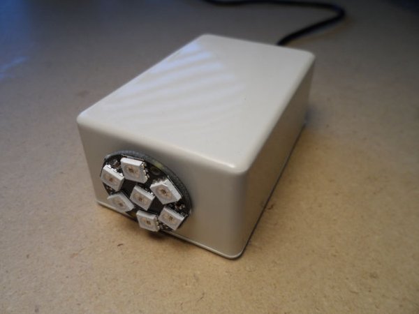
First I found a pre-built inexpensive module containing all the NeoPixels I desired. The original project hand wired up four. I choose a unit with seven LEDs. As I have a Large screen TV and thick drapes, I also increased, in the software, the maximum ‘On’ level driving the LEDs. If the unit is too bright to be effectively realistic in your use, you can lower the setting of ‘LED_BRIGHT’ and ‘LED_MIN’ in the software.
The unit is designed with a photocell so it only operates at night.
I made several Improvements of the simulation of a television’s light output during a typical TV show or movie. I put a fair amount of comments in the code explaining what was being done & why.
Step 1: Parts
The parts you’ll need are:
- Any Arduino MCU (I recommend: Nano 3.0) less than $3)
- NeoPixel WS2812 RGB LED Ring ($2) or string of say 4 to 10 LEDs
- a LDR Light-Dependent Resistor (Photoresistors)
- a 1000 ohm resistor.
- optionally some sort of container (e.g.)
- various equipment and tools (the usual stuff … PC, cables, wires, strippers …)
I have seen other project using NeoPixels in conjunction with capacitors. Presumably to eliminate erratic behavior. Erratic behavior on the part of the NeoPixels for the most part would be desirable in this application, so I have forgone the need for such capacitors.
As I see it additional variable resisters and switches can only provide marginal value to this device, while complicating fabrication and software implementation. So they are not used. On the other hand, you may need to change the software settings controlling the detection of night time, which activates the device. But this should be a one time adjustment. If desired the 1K could be replace with perhaps a 10K variable resisters.
Here is a simplistic diagram of how these parts interconnect for this project.
Nano MCU pin
D12 ———- ‘IN’ on the NeoPixel module
V5 ———- VCC ”
GND ——— GND ”
and
V5 —- Photoresistor —- A1 —- 1K resistor —- GND
I use what ever USB AC adapter is handy to power my unit.
If, in your ‘I made it’ project you use more LEDs be sure your power supply can handle it. Each of the 3 LED segments in a NeoPixel can use up to 20ma. So that 60ma per NeoPixel. I then need 7 times that to power my light output (i.e. 420ma). A 1A USB AC adapter will handle that easily. That current will only go through a large diode on the Nano board and out the V5 pin. This too will be fine.
Read more: Fake TV Security Light