
Summary of Fidget Spinner RPM Counter
This article details a DIY project to build an RPM counter for a fidget spinner using an Arduino Uno and a Hall-Effect sensor. The system detects rotation speed by sensing a neodymium magnet attached to the spinner, displaying real-time data on an LCD screen while providing visual feedback via an LED. The author emphasizes using the specific A3144 sensor over generic modules to avoid false readings caused by harmonic interference.
Parts used in the Fidget Spinner RPM Counter:
- Fidget Spinner
- Neodymium magnet
- Arduino Uno
- LED + resistor 220 Ohm
- Hall-Effect Sensor - a3144
- Resistor 10 k
- Wires
- Breadboard
- LCD 1602
Hi everyone! This is my next project, Fidget Spinner RPM Counter or Arduino Tachometer with Hall-Effect Sensor.
1: Requirements
Parts Required:
- Fidget Spinner
- neodyimium magnet
- Arduino Uno
- LED + resistor 220 Ohm
- Hall-Effect Sensor – a3144
- resistor 10 k
- Wires
- Breadboard
- LCD 1602
2: Hall-Effect Sensor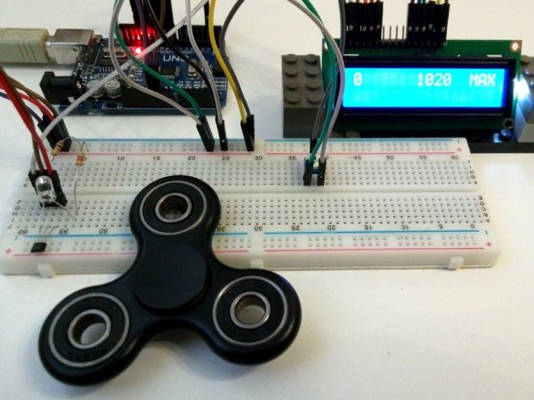
Using Hall-Effect Sensor we can measure the speed of rotation. I used Hall-Effect Sensor – a3144.
RPM (Revolutions per minute) – the number of revolutions per minute. Revolutions per minute – a unit of measurement of rotational speed: the number of complete rotations made by the body (fidget spinner, wheel etc.) around a fixed axis. Used to describe the speed of rotation of the mechanical components in the mechanisms and machines.
3: How does it work?
To measure the speed of rotation on the Fidget Spinner must be mounted a part of neodyimium magnet that affect the Hall sensor after each complete turn of the Spinner.
4: Indication
The presence of a magnetic field is indicated on the LED.
LCD 1602 indicates current RPM, maximum RPM and tachometr bar (from 0 up to 1260rpm). 1260 rpm is my personal record.
Also you can use Arduino IDE serial port.
5: Notes
I used a Hall-Effect Sensor A3144 and it worked well just connected to the pin 2 of Arduino Uno board. Also I tried to use a Hall-Effect Arduino module just like this one and it worked very bad.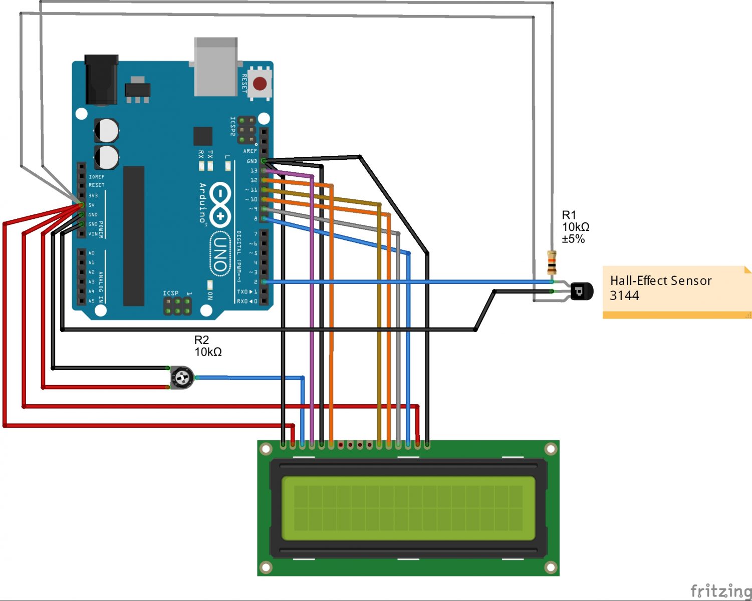
I recommend not using this module bacause of false harmonics.
Thank you all! Please, write in comments about your Fidget Spinner RPMs!
For more detail: Fidget Spinner RPM Counter
-
What components are required to build this project?
You need a fidget spinner, neodymium magnet, Arduino Uno, LED with 220 Ohm resistor, Hall-Effect Sensor A3144, 10k resistor, wires, breadboard, and LCD 1602. -
How does the Hall-Effect sensor measure rotation speed?
A neodymium magnet is mounted on the spinner so it affects the Hall sensor after each complete turn, allowing the system to calculate revolutions per minute. -
Which specific Hall-Effect sensor model did the author use?
The author used the Hall-Effect Sensor A3144 connected directly to pin 2 of the Arduino Uno board. -
Can I use a generic Hall-Effect Arduino module instead of the A3144?
No, the author recommends against using generic modules because they produce false harmonics and work very poorly compared to the A3144. -
What information does the LCD 1602 display?
The LCD shows the current RPM, maximum RPM achieved, and a tachometer bar ranging from 0 up to 1260 rpm. -
Is there a way to view the data without the LCD screen?
Yes, you can also use the Arduino IDE serial port to monitor the data. -
What is the purpose of the LED in this circuit?
The LED indicates the presence of a magnetic field whenever the sensor detects the magnet passing by. -
What is the highest RPM recorded during the project testing?
The author's personal record for the setup was 1260 rpm.
