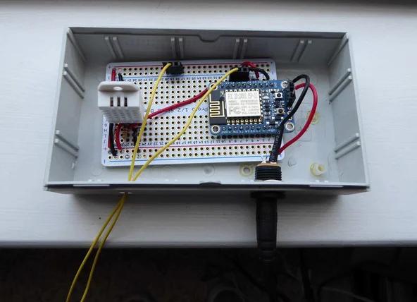
My basement gets wet when it rains a lot so I wanted a way to monitor it.
I decided to try using an ESP8266 as it has built in WiFi. I paired that with a DHT22 Humidity & Temperature Sensor and a float sensor to monitor my sump pump. Using the ESP8266 is easy enough as you can just use the Arduino IDE to program it. Besides the parts below you will need access to WiFi Dweet.io and Freeboard.io. These two web services make it easy to create a dashboard with your data.

Parts List
10k resistor
Hookup wire
Step 1: Arduino IDE Setup
If you already have Arduino setup for using ESP8266 you can skip this step.
Use a vs 1.6.4 or greater of the Arduino IDE. You can download the latest version here.
Open the new Arduino IDE and go to the preferences page.
At the bottom under Additional Boards Manager URLs add this URL.
http://arduino.esp8266.com/stable/package_esp8266c…
Then go to Board Manager under Tool / Board Manager and install the new ESP8266 package.
Select the appropriate board under tools and you should be ready to upload your code.
Note you need to put the ESP8266 into bootloader mode.
Hold down the GPIO0 button and at the same time click the RESET button and release it. Then release the GP100 button and you should see the red led dimly lit. This means you are now ready to upload code.
For this project you will also need the DHT library which is on Github. Grab it and install it now.
You may need to restart the Arduino IDE to see it.
Step 2: Breadboard Setup

Now we will setup the circuit on a breadboard first and later solder the circuit to a perfboard.
If you haven’t soldered the header pins onto the ESP8266 yet, do it now. If you are new to soldering header pins, see our tutorial How To Solder Header Pins. We also soldered on the 6 pins on the end so we could use FTDI / USB cable to program and power it.
Now put your ESP8266 onto the breadboard so that it straddles the middle gap. Attach the FTDI cable and try uploading the ESP8266 blink example. Remember to put in bootloader mode first by pressing the GP100 button and then the reset button. You should see the red led dimly light up.
Once that is working unhook the FTDI cable from the ESP8266 and add the DHT22 Humidity Sensor.
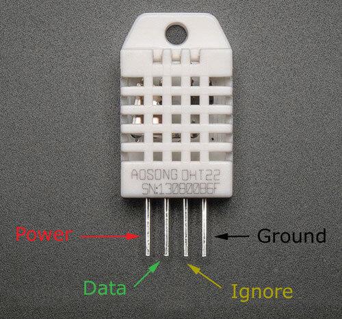
The DHT22 sensor has four pins as shown in the image above.
The leftmost pin is power. Next is the data pin. Ignore pin 3 and pin 4 is ground.
You will need to place the 10K resistor between power and the data pin to act as a pullup.
Now connect the FTDI cable to the ESP8266 and then go to the Arduino IDE. Open the example DHT Sensor Library / DHTtester under File / Examples and test it out.
Once this is working you can add the float sensor. One wire goes to ground and one wire goes to pin 4.
Step 3: Coding & Dweet
Now copy the text file ESP8266 Humidity Temp Monitor and paste it into a new sketch window.
You will need to make a few changes. In these two lines near the top change YourWifi and YourPassword to whatever your WiFi and password are.
const char* ssid = “YourWiFi”;
const char* password = “YourPassword”;
Under the function postData change the following line.
http.begin(“http://dweet.io/dweet/for/insertyouruniquenamehere?”);
Change insertyouruniquenamehere to a unique name to identify you on Dweet.
You can test out names on https://dweet.io/play/ .
Try doing POST / dweet/for/{thing}.
In the field for JSON just put {} to test it out.
To see your Dweets, go to https://dweet.io/follow/yournamehere and change yournamehere to the name you made up.
Now put your Dweet name into the code and upload the new version. What a few minutes and you should see new Dweets.
Step 4: Freeboard

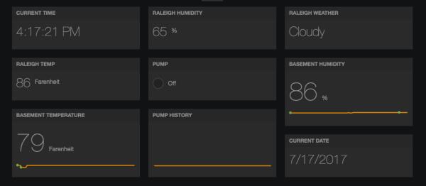
This is the last step Go to your Dweet follow page https://dweet.io/follow/yournamehere and at the top right there should be an orange button that says Create A Custom Dashboard.
This part is pretty straight forward and you can add or remove panes. The nice thing is they have some pre-made panes like time and weather for you. That’s it, you are done. At this point we left our breadboard setup alone and soldered up the circuit onto perfboard. See our tutorial Breadboard To Perfboard on how to do this.
The nice thing about this setup is you can add or remove sensors and easily update the dashboard.
If you decide to add new sensors you will also need to update the following of code under postData():
snprintf ( temp, 400, “{\”Temperature\”:%02d,\”Humidity\”:%02d,\”Pump\”:%01d}”, f, h, p);
This was probably the hardest thing to figure out. Remember Dweet is expecting to get JSON.
Happy tinkering and visit us at The Soldering Station.
Source: ESP8266 Basement Monitor
