The main purpose of this project was to build a robot that would differentiate itself from already existing robots, and that could be used in a real and innovative area.
Based on personal experience, it was decided to build a car-shaped robot that would be implemented in an Escape Game. Thanks to the different components, the players could switch on the car by solving a riddle on the controller, control the trajectory of the car, and get a key on the way in order to escape the room.
As this project was part of a Mechatronics course given at Université Libre de Bruxelles (U.L.B.) and Vrije Universiteit Brussel (V.U.B.), Belgium, a few requirements were presented at the beginning, such as :
- Using and combining fields of mechanics, electronics and programming
- A budget of 200€
- Having a finished and working robot that brings something new
And as it was going to be used in real-life escape game sessions, sometimes multiple sessions in a row, a few more requirements were needed to be fulfilled :
- Autonomy : finding a way to make the robot semi-autonomous to respect the game constraints
- User-friendly : easy to use, presence of a screen with feedback of the camera
- Robustness : strong materials capable of absorbing the shocks
- Safety : players not in direct contact with robot
Step 1: Main Concept & Motivation
As explained in the introduction, the main concept of this project is to create and build a semi-autonomous robot, first controlled by the players of the escape game, then capable of taking the control back from the players.
The principle is the following :
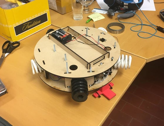
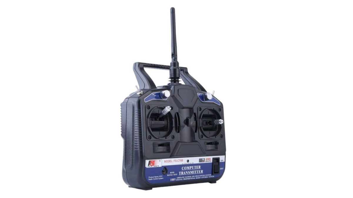
Imagine you are locked in a room with a group of friends. The only possibility to get out of the room is to find a key. The key is hidden in a maze located under your feet, in a dark intermediate floor. To get that key, you have in your possession three things : a remote controller, a map, and a screen. The remote controller enables you to control a car already in the intermediate floor, by solving a riddle imagined on the existing control buttons of the remote. Once you have solved that riddle, the car is turned on (cfr. Step 5: Coding – main function named ‘loop()’), and you can start guiding the car through the maze with the help of the given map. The screen is there to display live what the car sees, thanks to a camera fixed in front of the robot, and therefore help you see the trajectories and more importantly the key. Once you have got the key thanks to a magnet on the bottom of the robot, and once you have reached the end of the maze, you are capable of taking the key and escaping from the room you were locked in.
The main components of the robot therefore are :
- Riddle to be solved on remote controller
- Control of the robot by the players with remote controller
- Control display based on video filmed live by the camera
Because in such games the main constraint is time (in most escape games you have between 30 minutes and 1 hour to get out to succeed), a sensor is attached and connected at the base of the robot so that if you, as players, exceed a given time (in our case 30 minutes), the robot takes the control back and finishes the parcours by itself, so that you have a chance of getting the key of the room before the timer of the game goes off (in our case 1 hour)
Also, as the car is in a completely dark room, LEDs are fixed not far from the sensor to help it read the signal from the ground.
The desire behind this group project was to base ourselves on what already exists on the market, modify it by adding a personal value, and be able to use it in some fun and interactive field. As a matter of fact, after being in contact with a successful Escape Room in Brussels, Belgium, we discovered that escape games are not only more and more famous, but that they often lack interactivity and that customers complain not to be enough “part of” the game.
We therefore tried to come up with an idea of a robot that would meet the given requirements while inviting the players to really be part of the game.
Here is a summary of what happens in the robot :
– The non-autonomous part : a remote controller is linked to Arduino through a receiver. Players control the remote and therefore control the Arduino which controls the motors. The Arduino is turned on before the game starts, but it enters the main function when players solve a riddle on the remote controller. An IR wireless camera is already turned on (turned on at the same time as the “whole” (controlled by the Arduino) when switch on/off turned on). Players guide the car with remote controller : they control the speed and the direction (cfr. Step 5: flowchart). When the timer that starts when the main function is entered is equal to 30 minutes, the control from the controller is disabled.
– The autonomous part : the control is then managed by the Arduino. After 30 minutes, the IR line tracker sensor starts following a line on the ground to finish the parcours.
Step 2: Material & Tools
MATERIAL
Electronic parts
- Microcontroller :
- Arduino UNO
- Arduino motor shield – Reichelt – 22.52€
- Sensors :
- IR line tracker – Mc Hobby – 16.54€
- Batteries :
- 6x 1.5V battery
- Other :
Mechanical part
- DIY car chassis kit – Amazon – 14.99€
- Used :
- 1x switch
- 1x castor wheel
- 2x wheels
- 2x DC motor
- 1x battery holder
- Not used :
- 1x car chassis
- 4x M3*30 screw
- 4x L12 spacer
- 4x fasteners
- 8x M3*6 screw
- M3 nut
- Used :
- Magnet – Amazon – 9.99€
- Bolts, nuts, screws
- M2*20
- M3*12
- M4*40
- M12*30
- all respective nuts
- 3D printed pieces :
- 5x springs
- 2x motor fixation
- 1x L-shape line tracker fixation
- Laser cut pieces :
- 2x round flat plate
- 5x rectangle small flat plate
TOOL
- Machines :
- 3D printer
- Laser cutter
- Screwdrivers
- Hand driller
- Lime
- Electronics solder
Step 3: (Laser) Cutting & (3D) Printing
We used both laser cutting and 3D printing techniques to obtain some of our components.
You can find all the CAD files in the file .step below.
Laser cutter
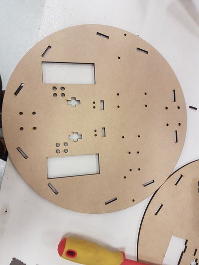
The two main fixation pieces of the robot were laser cut :
(Material = MDF cardboard of 4mm)
– 2 round flat disks to make the basis (or chassis) of the robot
– Several holes on the two disks in order to accommodate mechanical and electronic components
– 5 rectangle small plates to fix the springs between the two chassis plates
3D printer (Ultimakers & Prusa)
Different elements of the robot were 3D printed, in order to give them resistance and flexibility at the same time :
(Material = PLA)
– 5 springs : note that the springs are printed as blocks, so that it is necessary to file them to give them their ‘spring’ shapes !
– 2 rectangular hollowed parts to fix the motors
– L-shape piece to accommodate the Line tracker
Source: Escape Robot : RC Car for an Escape Game