Summary of “Wooden” Desktop Clock *Modern Looking*
This project builds a wooden-look desktop clock using a 4-digit seven-segment display, Arduino Pro Mini, RTC, temperature and humidity sensors, and a vibration sensor to switch displays. The display appears through wood-texture vinyl while retaining brightness. The guide covers soldering, wiring, programming via USB-TTL, and a toggle scheme where vibration cycles time → temperature → humidity. Calibration tip: adjust a TimeSpan line in the code if the clock is off.
Parts used in the Wooden Desktop Clock:
- Arduino Pro Mini
- 4 digit 7 segment display (8402AS version)
- Real time clock module
- Vibration sensor
- Temperature sensor
- Micro USB port module
- USB uploader (USB to TTL programmer)
- Wooden textured vinyl sticker (two pieces)
- Prototyping board 4x6 cm
- Soldering iron
- Hot glue gun
Hi everyone, this is my second instrucatable! This time we are going to build a wooden clock with temperature and humidity display. Like shown in the picture, our the time will be displayed through the “wood”.
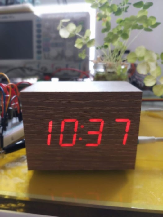
Since light isn’t strong enough to pass a piece of wood, we are going to use wood texture vinyl stickers make our product looks like wood while the number display stays bright and clear.
This project is more about DIY-ing, so you are actually building the whole thing yourself.
Special skills needed:
Be able to do soldering
Have basic understanding in electronics and programming (Arduino)
If you don’t like to do too much soldering, you can build a easy version of this clock but you will miss the temperature and humidity feature. For the easier version, start from step 5.
THAT’S ALL, HOPE YOU ENJOY THE PROGRESS OF DIY-ing!
Step 1: Features of the Clock
I wanted a temperature and humidity display in my clock, but i don’t want to make two extra displays for temperature and humidity. So I thought to make the 4 digit display to also show the temperature and the humidity.
To make the display change from displaying time to displaying temperature, we need something like a button to tell the system to display the different variables.
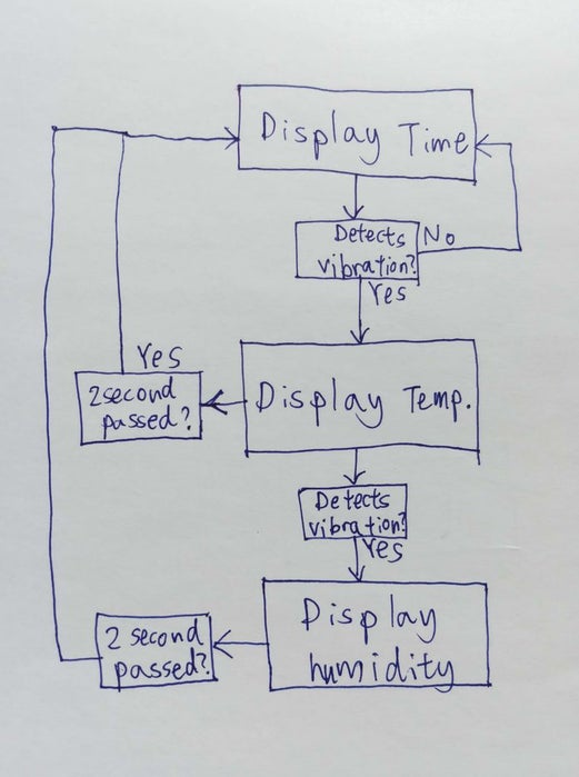
In my system, I used a vibration sensor, which obviously detects vibration.
According to the photo, once the sensor detects a vibration, the system(Arduino) will switch from displaying time to displaying temperature, at the same time, the system counts 2 second. During that 2 seconds, if the system detects another vibration, the display start displaying humidity.
Step 2: Gathering the Materials & Components
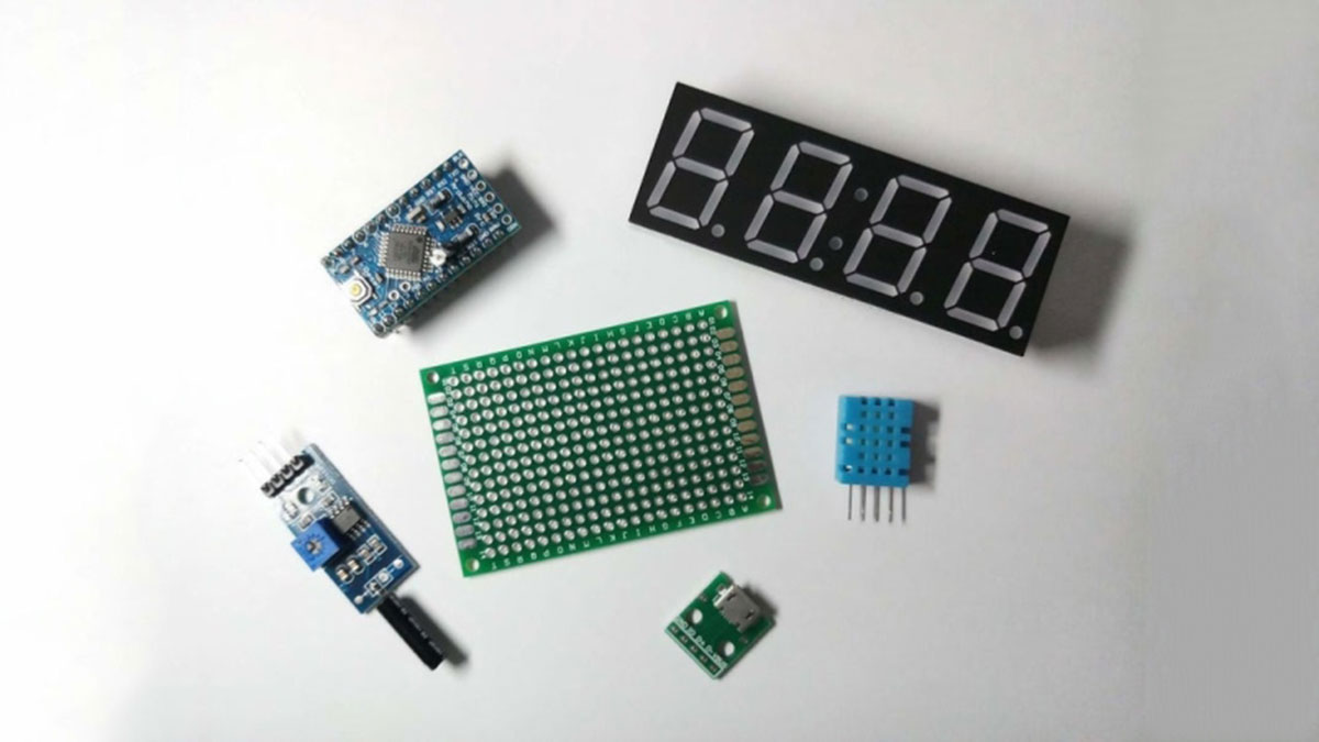
Here is the list of the components you will need:
2. 4 digit 7 segment display (choose the 8402AS version)
7. USB uploader
8. Wooden textured vinyl sticker (buy two of them)
Also a mini prototyping board:
You also need a soldering iron and a hot glue gun!!! You can get those in hardware shops!
If you want to get into Arduino and programming you might want to also get the Arduino starter kit:
Step 3: Soldering the Components
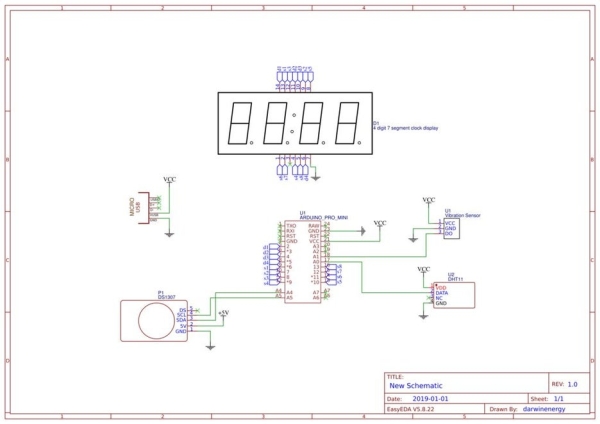
Now you should have all your components ready, because it’s soldering time!
Follow the design like shown in the first picture, or visit this site to see my original design.
Tips:
I don’t like to connect wires directly to a prototype board, because it’s too fragile. My way of connecting wires to a prototyping board is to use male and female connectors, like shown in the second picture.
To solder, you first heat up the surface by putting your soldering iron onto the prototyping board, wait 1~2 second and apply your solder to the board, remember to keep your soldering iron on the prototyping board while applying solder.
Most solder comes with flux, which will clean the surface of the prototyping board and make the solder surface shiny. But when the flux evaporate they will become harmful gas, so you may want to hold your breath or use a fan to suck away the harmful gas.
Remember to take your time and pay 100% attention since you won’t want your 380 degree (Celsius) solder iron accidentally touch your skin.
I also left some finished picture here feel free to take a look.
If you think this is too complicated, build the easy version and start at step 5.
Step 4: Programming It!
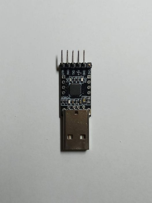
To program a micro-controller, we need to use a computer’s USB port. To do that, we need to use our USB to TTL programmer, yes, the one in the first picture.
Do the following connections:
Arduino side———-Programmer side
VCC————————————–+5V
GND————————————-GND
GRN————————————-DTR
TX——————————————RX
RX——————————————TX
Upload the attached code to the Arduino Pro Mini.
*IMPORTANT*
After uploading the code, remember to power it on and test it, if the clock is in synchronized with the real time. But if it is not, do the following:
Edit the code, at line 83: DateTime nowactually (now + TimeSpan(0, 0, 25, 0));
My clock is 25 minutes slower than real time. So I made the incorrect time to go back to real time by adding 25 more minutes to the incorrect time, and put it into a new variable.
**example** if your clock is 50 minutes slower than the actual time, you do: TimeSpan(0, 0, 50, 0);
**example** if your clock is 15 minutes faster than the actual time, you do: TimeSpan(0, 0, -50, 0);
Remember to choose the correct PORT from the TOOLS drop down menu!
**whispers** Google is still your best friend!
Source: “Wooden” Desktop Clock Modern Looking
- How does the clock switch from time to temperature display?
The vibration sensor detects vibration and the Arduino switches from displaying time to temperature, and a second vibration within 2 seconds switches to humidity. - Can I build an easier version without soldering?
Yes, you can build an easier version starting at step 5 but you will miss the temperature and humidity feature. - What USB connections are required to program the Arduino Pro Mini?
Connect VCC to 5V, GND to GND, GRN to DTR, TX to RX, and RX to TX on the USB to TTL programmer. - How do I fix the clock if it is not synchronized with real time?
Edit the code at the specified TimeSpan line to add or subtract minutes to correct the offset and re-upload the code. - Which display version should I choose?
Use the 8402AS version of the 4 digit 7 segment display as recommended in the materials list. - Are there any safety tips for soldering?
Heat the board before applying solder, be aware of flux fumes and use ventilation, and avoid touching the hot soldering iron. - How is the wood appearance achieved while keeping the display visible?
Wood texture vinyl stickers are applied so the display shows through the vinyl while remaining bright and clear. - What extra components help make wiring more robust?
Use male and female connectors between wires and the prototyping board instead of soldering wires directly to the board.