
Summary of Easy, Reversible Motor Control for Arduino (or any Microcontroller) using arduino
This article details the "RAT Controller," a simple, low-cost DIY circuit for forward and reverse motor control using only three main components: a DPDT relay and two TIP120 transistors. Designed for Arduino or other microcontrollers, it supports PWM speed control and requires just two control pins. The project can be assembled without a circuit board in about 15 minutes for under $9, handling up to 5 amps peak current with a minimum operating voltage of 7.5V.
Parts used in the RAT Controller:
- 12VDC Coil DPDT Miniature PC Relay (Radio Shack Part: 275-249 or OMI-SH-212D)
- 2 x TIP120 Darlington Transistors (Radio Shack Part: 276-2068)
- 2 x 220 Ohm Resistors
- Optional TO-220 size heatsink (Radio Shack 276-1363) with #6 screw and nut
- Soldering Iron and solder
- 22 Gauge Solid Core Hookup Wire (Radio Shack Catalog # 278-1221)
This project uses just three main components to provide forward and reverse control for a single motor. You can easily interface it to an Arduino or any other microcontroller.
It’s so simple – you can wire it up “free-form” without a circuit board in about 15 minutes.
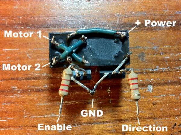
Features:
All parts available at Radio Shack for under $9
Supports PWM for variable speed control
Handles up to 5 amps peak / 2.5 amps continuous (5 amps continuous with heatsink)
Controlled using just two pins – “enable” and “direction”
Limitations:
Requires at least 7.5 volts to operate
Relay is rated for “only” 100,000 cycles and may not be appropriate for some high vibration projects
Doesn’t provide motor “braking”
The most common way to provide reversible motor control is with an H-Bridge. A basic H-Bridge is made up of 4 transistors – but commonly end up requiring more like 10 components when you include things like flyback diodes and secondary transistors.
I wanted something simpler for a CNC project I’m working on – so I came up with this design. I’m fairly sure I’m not the “inventor” of this circuit – but it’s not widely documented. As far as I can tell it doesn’t have a name.
I am hereby naming it the RAT Controller. RAT being an acronym for Relay And Transistors.
Step 1: Stuff You’ll Need
All parts are available at Radio Shack – expect to pay a bit under $9 for the main components.
The same parts are available online for under $4.
12VDC Coil DPDT Miniature PC Relay
Radio Shack Part: 275-249
If purchasing online – try searching for “OMI-SH-212D”
2 x TIP120 Darlington Transistors
Radio Shack Part: 276-2068
2 x 220 Ohm Resistors
Values do not need to be exact.
Optional: Heatsink
A TO-220 size heatsink such as Radio Shack 276-1363 will allow this motor controller to provide 5 amps continuously as opposed to just peak. You’ll also need a #6 screw and nut. See the final “Notes” step for information on installing or making your own heatsink out of a pop can.
You’ll also need:
Soldering Iron
And solder – any gauge is fine.
Hookup Wire
You’ll need some kind of hookup wire to make connections and interface with your microcontroller.
22 Gauge Solid Core Hookup wire works well and easily fits into Arduino headers.
Available at Radio Shack – Catalog # 278-1221
Step 2: Schematic and Theory of Operation
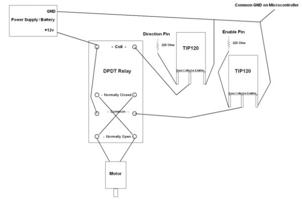
This circuit uses a DPDT (Double Pole Double Throw) relay to switch which direction the motor is turning.
The motor is connected to both normally closed and normally open (in reverse) sides of the relay. This in effect reverses the wiring whenever the relay is turned on or off.
Since the microcontroller can’t quite produce enough current to drive the relay – a transistor (TIP120) is used to switch it on and off.
The “Base” of the first TIP120 is the “Direction Pin” – turning it on and off switches the direction of the motor.
A second TIP120 switches power to common on the relay. This is used to turn the motor on and off.
The “Base” of the second TIP120 is the “Enable Pin” – turning it on causes the motor to actually run.
The enable pin may be switched on and off very quickly for PWM (pulse width modulation) speed control.
Both control pins are connected to the microcontroller via 220 Ohm resistors to limit current.
The minimum voltage to drive this circuit is determined by the “pickup” voltage of the relay. This is listed as 9.6v – but I’ve found it to function properly as low as about 7.5v.
Don’t worry if the schematic doesn’t make total sense. We’ll go through all the connections one-by-one.
Step 3: Bridge NO and NC Pins (Part 1)
Position the relay in front of you as shown in the picture.
Use a piece of hookup wire and your soldering iron to connect the pins as shown.
This connection bridges one of the Normally Open (NO) relay pins to one of the Normally Closed (NC) relay pins.
Step 4: Bridge NO and NC Pins (Part 2)
Again – use a piece of hookup wire and your soldering iron to connect the pins shown.
This connection bridges the other Normally Open (NO) and Normally Closed (NC) relay pins.
Step 5: Connect Coil Pin To Common Pin
One last time – use a piece of hookup wire and your soldering iron to connect the pins shown.
This connects one of the relay’s Coil pins to one of its Common pins. Both of these pins will later be provided with positive voltage.
Step 6: Connect TIP120 Collector to Relay Coil Pin
Solder the middle pin of one of the TIP120s to the relay pin on your lower right (as pictured).
This connects the TIP120 Collector pin to the relay’s other Coil pin.
Step 7: Nudge TIP120 Into Position
Carefully push the TIP120 towards your left and against the relay as shown.
This isn’t just cosmetic – the TIP120 needs to be in this position for a connection we’ll make later.
For more detail: Easy, Reversible Motor Control for Arduino (or any Microcontroller)
-
What is the RAT Controller?
It is a simple design named Relay And Transistors that provides forward and reverse control for a single motor using just three main components. -
How many pins are required to control the motor?
The controller is controlled using just two pins labeled enable and direction. -
Can this circuit support variable speed control?
Yes, the enable pin may be switched on and off very quickly for PWM speed control. -
What is the minimum voltage required to operate the circuit?
The circuit requires at least 7.5 volts to operate, though the relay pickup voltage is listed as 9.6v. -
How much current can this motor controller handle?
It handles up to 5 amps peak and 2.5 amps continuous, or 5 amps continuously if a heatsink is installed. -
Is a circuit board necessary for assembly?
No, you can wire it up free-form without a circuit board in about 15 minutes. -
Does the RAT Controller provide motor braking?
No, the project does not provide motor braking capabilities. -
What type of transistors are used in this design?
The design uses two TIP120 Darlington Transistors to switch the relay and power to the motor.
