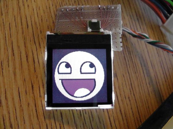
Nokia manufactures a wide variety of cell phones and many of their cheaper phones contain simple LCD’s which may be used in microcontroller projects. There is one particular LCD model that is used in a wide variety of their phones and is often referred to as simply a “Nokia LCD”, or “Nokia 6100 LCD”. I used to use a Nokia 2600 phone and whenever I upgraded I took the Nokia apart to remove its LCD. This LCD appears to be the same one that is sold as “Nokia 6100 LCD” and I was able to get it up and running with a bit of work using an AVR.
SparkFun sells them if you do not already have one,
http://www.sparkfun.com/products/569
You will need some sort of breakout board in order to connect the display. Sparkfun sells several (a standard breakout, an Arduino shield, an Olimex module, etc) as well as the bare surface-mount connector. Since all of SparkFun’s boards include the LCD, I just bought the connector and made my own breakout board since I already had the LCD.
The connector:
http://www.sparkfun.com/products/570
Step 1: LCD Connector and Breakout Board
If you don’t have a breakout board, you need to first make some sort of connector for the LCD. My first attempt was to solder thin magnet wire to each leg of the connector with a fine-tip soldering iron. This took several tries but eventually I got it connected. I then applied generous amounts of super glue to make sure it wouldn’t come apart and soldered on some thicker wires to connect to the microcontroller.
For cleaner and more practical uses, I eventually made a small breakout board for the connector that can be printed and etched using the laser printer toner transfer method. Make sure not to put too much pressure on the transfer or the traces can be pressed together. If this happens, you can try cutting the toner away with a sharp knife, but you’ll probably end up breaking the toner trace and have to start over.
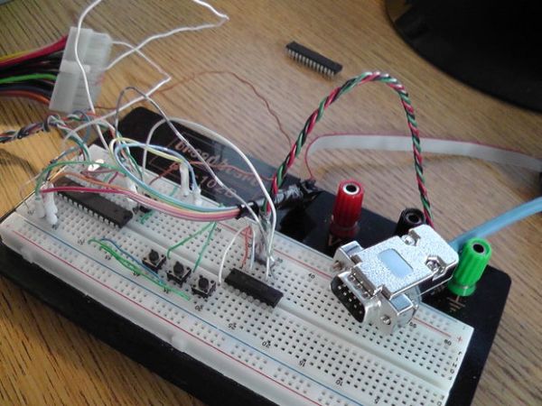
I hand-soldered the connector to the finished PCB and then added some breakaway pin headers so that the board may be breadboarded or socketed into projects while being easily removable.
If you don’t have a breakout board, you need to first make some sort of connector for the LCD. My first attempt was to solder thin magnet wire to each leg of the connector with a fine-tip soldering iron. This took several tries but eventually I got it connected. I then applied generous amounts of super glue to make sure it wouldn’t come apart and soldered on some thicker wires to connect to the microcontroller.
For cleaner and more practical uses, I eventually made a small breakout board for the connector that can be printed and etched using the laser printer toner transfer method. Make sure not to put too much pressure on the transfer or the traces can be pressed together. If this happens, you can try cutting the toner away with a sharp knife, but you’ll probably end up breaking the toner trace and have to start over.
I hand-soldered the connector to the finished PCB and then added some breakaway pin headers so that the board may be breadboarded or socketed into projects while being easily removable.
Step 2: Electrical Interfacing
Pinout:
1: Vcc (3.3V)
2: Reset
3: Data
4: Clock
5: Chip Select
6: Vcc (3.3V)
7: Unused (Not Connected)
8: Ground
9: Ground (Backlight LED -)
10: Backlight LED +
Since the LCD protocol is 9-bit SPI, you cannot use the hardware SPI interface found on many microcontrollers (including the AVR series microcontrollers) as they often only support 8-bit mode. This means that you will probably have to implement a software SPI output. Electrically, this means you can connect the four control lines to any unused I/O pins on your microcontroller. Your microcontroller must be running at 3.3V to connect the lines directly, otherwise add 10K ohm resistors on each line to limit the current going into the LCD.
Step 3: LCD Protocol – Initialization (Phillips PCF8833 Only!)
The LCD has many functions that are available by sending commands over the SPI interface. The important ones are explained here and will allow you to get your LCD up and running. A full set of commands is listed in the PCF8833 datasheet here:
http://www.nxp.com/acrobat_download2/datasheets/PCF8833_1.pdf
The 9th bit is the command flag. If set to 0, the data byte is interpreted as a command. If 1, the data byte is interpreted as data. Data may be sent after issuing an appropriate command.
Before you can write to the LCD, it must be initialized. First, the Reset line must be pulled low for around 100ms and then raised high again. The Reset line must remain high during operation. Then, a sequence of commands must be sent, in the following order:
SLEEPOUT (Hex 0x11) – Exits LCD sleep mode
BSTRON (Hex 0x03) – Turns on booster voltage
COLMOD (Hex 0x3A) – Sets pixel format to the following data byte
Data 0x03 – The pixel format 0x03 is 12 bits per pixel
MADCTL (Hex 0x36) – Sets several LCD params – [<Mirror Y>, <Mirror X>, <Vertical Write>, <Bottom to Top>, <BGR/RGB>, -, -, -]
Data 0xC0 – Flips display upside down (my LCD was mounted upside down), uses RGB color format
SETCON (Hex 0x25) – Set Contrast to following data byte
Data 0x40 – This contrast value works fairly well for my LCD, adjust if yours does not display well
DISPON (Hex 0x29) – Turns on display
Step 4: LCD Protocol – Drawing (Phillips PCF8833 Only!)
Continuing with the protocol, once the LCD is initialized it is ready to draw. Drawing works by first defining a region to draw and then streaming pixel data to fill that region. It is confusing at first, but if done properly is more efficient than pixel-by-pixel drawing. A region is simply a rectangular area on the screen. We’ll say it begins at point (X1,Y1) and ends at point (X2, Y2). Once defined, the LCD controller will fill in pixels from left to right starting at (X1, Y1). When it reaches the edge of the region, it will jump to the next line [in my example, (X1, Y1+1) ]. It does this until it reaches (X2, Y2) at which it stops accepting data. If you only want to draw one pixel, you simply set (X1, Y1) and (X2, Y2) to the pixel you want to draw. This defines the region as a single pixel. Any data sent after the first pixel’s worth of data is discarded.
To define a region, you must send these commands in the following order:
PASET (Hex 0x2B) – Page Address Set
Data Y1 – The starting Y position
Data Y2 – The ending Y position
CASET (Hex 0x2A) – Column Address Set
Data X1 – The starting X position
Data X2 – The ending X position
RAMWR (Hex 0x2C) – RAM Write – Start sending pixel data after this command
<Pixel Data> – Formatting described below
After the screen is ready to accept pixel data, you must send color data for each pixel in order. In the default color mode (0x03, 12 bits per pixel) color data uses 12 bits. This means that you can send 2 pixels worth of data for every 3 bytes. If you are only sending one pixel, you only need to send 2 bytes. The 2-pixels-per-3-bytes format is shown below:
RRRR GGGG | BBBB RRRR | GGGG BBBB
If only sending one pixel, you may use this format instead:
XXXX RRRR | GGGG BBBB (X means “don’t care”, can be either 0 or 1, these bits are discarded)
In C, you may use this code to output 2-pixels-per-3-bytes format, color1 and color2 are 16-bit values (ints in AVR GCC)
(color_lcd_send_data(char dat) is a function that outputs a data byte to the LCD)
color_lcd_send_data(color1 >> 4);
color_lcd_send_data(((color1&0x0F)<<4)|(color2>>8));
color_lcd_send_data(color2);
This code is simplified for 1-pixel-2-bytes format for single-pixel writes:
color_lcd_send_data(color >> 4);
color_lcd_send_data(color<<4);
For more detail: How To Use a Nokia Color LCD!