Summary of Drone The Quadcopter
Drone The Quadcopter is a beginner-friendly F450 X-frame UAV project using a Flysky FSCT6 radio for 800 m–1.2 km range. The build teaches long-range aerial vehicle basics for applications like search and rescue and reporting. Steps include mounting A2212 motors to the F450 arms, soldering ESC power wires to the bottom PCB, installing legs, battery, RC receiver, covering the top support, placing the KK2.1 flight controller, and connecting motor phase wires to ESCs (swap two wires to reverse motor direction).
Parts used in the Drone The Quadcopter:
- Flysky FSCT6 RC Transmitter and receiver
- KK2.1 Flight controller board
- F450 Quadcopter arm kit
- 4 X 1000KV A2212 BLDC motor
- 4 X ESC
- 4 X 1045 Propeller
- Four legs for quadcopter stand
- LiPo battery 2200mAh/35C
- LiPo battery charger
- Connecting cables
- Heat shrink tubes
“Drone The Quadcopter” is an featured UAV. I design my project with F450 arm in X-mode design. The full operation takes place via a Flysky FSCT6 remote control unit which gives a better operating range of 800 Meter to 1.2KM.
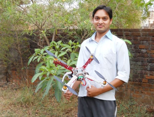
If you are a beginner in this field then you are on the right place. The ultimate goal of our project is to learn aerial vehicles which can be flyover a long height and over a long range communication. By learning this technology can be used for search and rescue, fire-fighting, law enforcement, military, and news reporting by being able to deploy aerial correspondence much faster than conventional helicopters.
Step 1: Watch Video
Step 2: Required Components
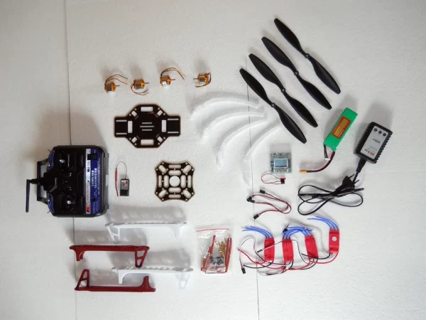
- Flysky FSCT6 RC Transmitter and receiver
- KK2.1 Flight controller board
- F450 Quadcopter arm kit
- 4 X 1000KV A2212 BLDC motor
- 4 X ESC
- 4 X 1045 Propeller
- Four legs for quadcopter stand
- LiPo battery 2200mAh/35C
- LiPo battery charger
- Connecting cables
- Heat shrink tubes etc.
Step 3: Connect Motors to Arm
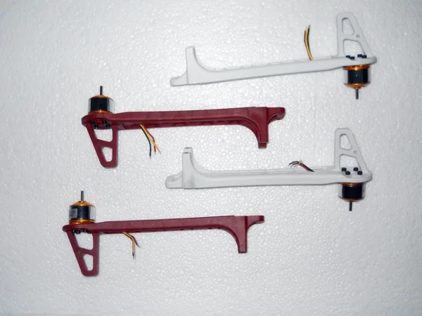
Start the project by connecting each motors to each arm with screws.
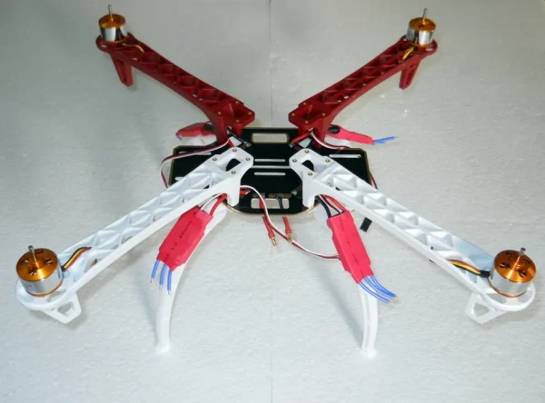
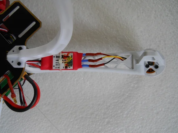
Step 4: Solder the ESC to the Bottom PCB
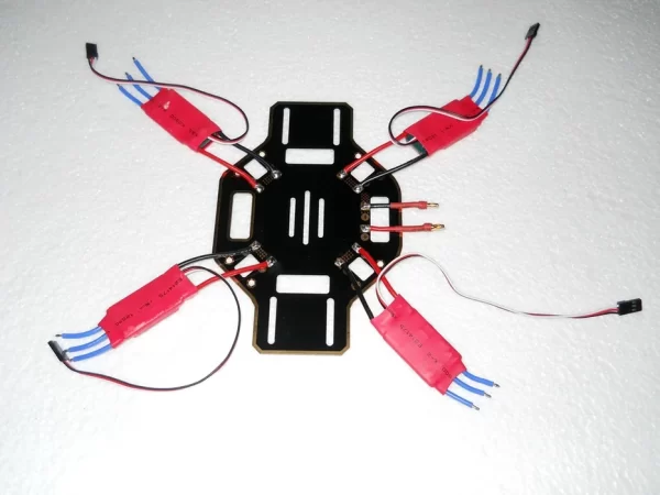
Solder the ESC(electronic speed controller) to the bottom support PCB. Remember to solder the power supply wires only.
Step 5: Connect Bottom PCB to Arm and Legs
Step 6: Install Battery and RC Receiver
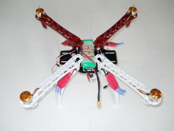
Step 7: Cover the Top Support
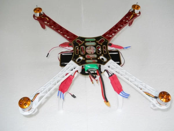
Step 8: Place the Flight Controller Board
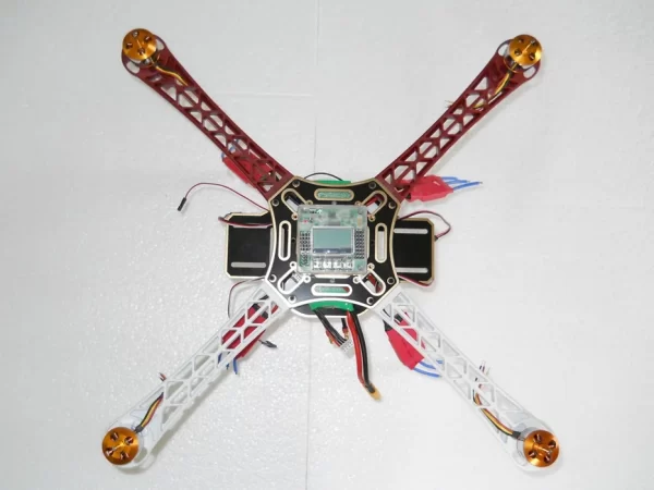
Place the flight controller board on the top supporting base using hot glue or any adhesive material.
Step 9: Soldering Motor Terminals to ESC
There are three terminals of motors. Connect these terminals to the terminals of ESC output. Two motor have a clockwise rotation and the rest two motors have a counter-clockwise rotation. After connection of motors and ESCs, if you want to change the direction of any motor then simply replace two terminals except the middle one.
Read more: Drone The Quadcopter
- What radio system is used for this quadcopter?
The Flysky FSCT6 RC Transmitter and receiver is used. - What flight controller board does the project use?
The project uses the KK2.1 flight controller board. - Which motors are specified for the build?
Four 1000KV A2212 BLDC motors are specified. - How are the ESCs connected to the power system?
Only the power supply wires of the ESCs are soldered to the bottom support PCB. - How do you change a motor direction?
To reverse a motor, swap any two of the three motor terminals except the middle one. - Where is the flight controller placed?
The flight controller board is placed on the top supporting base using hot glue or adhesive. - What battery is recommended?
A LiPo battery 2200mAh/35C is recommended. - What propellers are used?
1045 propellers are used for all four motors.