
Summary of Drawing an Arduino Circuit Diagram
The author used an Arduino Duemilanove and Fritzing to document and redesign a 7-segment LED counting circuit. They describe creating and editing parts (SVG), labeling pins for schematic clarity, and exporting PCB layouts (Gerber) for fabrication. A common-cathode 7-segment wiring and an Arduino sketch to count 0–9 are provided, plus brief praise and a wish for a snap-to-grid routing feature.
Parts used in the 7-Segment Arduino Counting Project:
- Arduino Duemilanove
- 7 Segment Red LED 0.3" Digital Display (RadioShack 276-075), common cathode
- Breadboard (implied for prototyping)
- Wires/jumpers (for connections)
- USB cable (for programming Arduino, implied)
- Power supply (Arduino power socket, implied)
- Fritzing software (for documentation, schematic, and PCB layout)
- svg-edit (browser-based SVG editor used to label pins)
I’ve been in possession of an Arduino Duemilanove for a couple of weeks. If you are unfamiliar with the Arduino, it is defined as “a platform for creating electronics prototypes using adaptable, user-friendly hardware and software”. The setup consists of a small microcontroller, a USB port for programming on a computer, a power socket for standalone power, and various digital and analog pins for linking LEDs, switches, and sensors.
It is reasonably priced, and there is a complimentary IDE accessible for coding. I did well, but I quickly struggled to remember my circuits. I would assemble a project on a breadboard, program it, and then take it apart to build a different circuit. When I attempted to return to a previous circuit, I had the software saved, but I couldn’t always remember how I had wired the circuit.
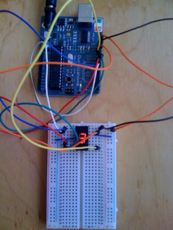
I looked for a tool to document my circuits and came across Fritzing. Using it is very easy. You select parts from a palette and arrange them by dragging and dropping. You can choose to work on either a breadboard view or a schematic view, and they will be synchronized automatically. It is easy to shape wires into curves to direct them along attractive routes.
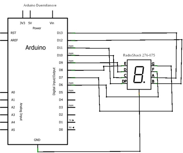
Displayed is an example of a configuration featuring the Arduino Duemilanove and a 7 Segment Red LED 0.3″ Digital Display (RadioShack 276-075).
Building this enabled me to experiment with another feature of Fritzing, since the basic components of the software included a 7 Segment LED that functioned as a numerical display with a common anode. Despite the lack of labeled pins, the tool still indicates the positioning of the anode/cathode, and my goal is to accurately recognize them. I changed the segment, adjusted the pin connections, and saved it as a new component. This was all straightforward and clear.
Then I decided I wanted to have the pins be labeled A, B, C so that it would show up in the schematic view. All the images are SVG, and I didn’t have an SVG editor handy, so I used svg-edit, an online browser based editor. I copied the “7-segment display.svg”, added the letters, saved it into a new svg file, and selected it within fritzing. I did need to close and reopen Fritzing for it to refresh the schematic which already had the old image on it, but I didn’t need to remove and re-add.
I’m still experimenting with Fritzing, but for something that I’ve only been using for an hour or so I’ve found it remarkably full featured and easy to use. It would be nice if it had a “snap to grid” feature that would recognize when I’m trying to route my wires horizontally and vertically and fix things when I’m just a little off. But that’s really just a nit – and maybe something it has and I just haven’t found yet.
One more thing that Fritzing can do is create a PCB layout in various formats, that can be used to manufacture the circuit boards. For example, you can export as a Gerber file and use a printed circuit board fabrication service like BatchPCB.
Lastly, in case you were looking for how to count from 0 to 9 on the above circuit over and over again, here’s the sketch
// Counting on a 7-Segment Red LED (common cathode) numerical display
// RadioShack 276-075 / Wiring
//
// arduino pin -> 7-segment LED pin -> anode
// 13 -> 14 -> A --A--
// 12 -> 13 -> B | |
// 11 -> 9 -> RHDP F B
// 10 -> 8 -> C | |
// 9 -> 7 -> D --G--
// 8 -> 6 -> E | |
// 7 -> 2 -> G E C
// 6 -> 1 -> F | |
// --D-- O
 int ledPins[]={0xDD,0x50,0xCE,0xDA,0x53,0x9B,0x9F,0xD0,0xDF,0xD3};
void setup()
{
for (int i=6;i<14;i++) {
pinMode(i,OUTPUT);
}
}
void loop()
{
for (int i=0; i<10; i++) {
displayNumber(i);
delay(500);
}
}
void displayNumber(int num)
{
for (int i=0; i<8; i++) {
digitalWrite(i+6, bitRead(ledPins[num],i));
}
}
int ledPins[]={0xDD,0x50,0xCE,0xDA,0x53,0x9B,0x9F,0xD0,0xDF,0xD3};
void setup()
{
for (int i=6;i<14;i++) {
pinMode(i,OUTPUT);
}
}
void loop()
{
for (int i=0; i<10; i++) {
displayNumber(i);
delay(500);
}
}
void displayNumber(int num)
{
for (int i=0; i<8; i++) {
digitalWrite(i+6, bitRead(ledPins[num],i));
}
}Source: Drawing an Arduino Circuit Diagram
- What Arduino board is used in the project?
The Arduino Duemilanove is used in the project. - Which 7-segment display is shown and what is its type?
The project uses a 7 Segment Red LED 0.3" Digital Display (RadioShack 276-075) and the sketch is for a common cathode display. - How are the 7-segment display pins connected to the Arduino pins?
The article lists Arduino pins 13,12,11,10,9,8,7,6 connected to display pins 14,13,9,8,7,6,2,1 respectively with corresponding segment labels A,B,RHDP,C,D,E,G,F. - Can Fritzing be used to edit part graphics and labels?
Yes, the author edited the 7-segment SVG using svg-edit and loaded the modified SVG into Fritzing to show labeled pins in the schematic. - Does Fritzing support PCB export for fabrication?
Yes, Fritzing can create PCB layouts and export formats such as Gerber for PCB fabrication services like BatchPCB. - Is there example code to count from 0 to 9 on the 7-segment display?
Yes, the article provides an Arduino sketch that cycles through numbers 0 to 9 using an ledPins array and displayNumber function with a 500 ms delay. - Do the breadboard and schematic views in Fritzing stay synchronized?
Yes, the article states the breadboard view and schematic view are synchronized automatically. - Did the author find Fritzing easy to use?
Yes, the author found Fritzing remarkably full featured and easy to use after about an hour of trying it.
