Summary of DIY USB Type-C Power Delivery Trigger Board
This article guides readers through building a DIY USB Type-C Power Delivery (PD) Trigger board capable of outputting 5V to 20V. The author compares a commercial board with a custom version using an ESP8266 and FUSB302, providing schematics, Gerber files, wiring diagrams, and code to help users decide if the DIY approach is worthwhile.
Parts used in the DIY USB Type-C Power Delivery Trigger Board:
- ESP8266
- FUSB302 board
- Power Delivery compatible power source
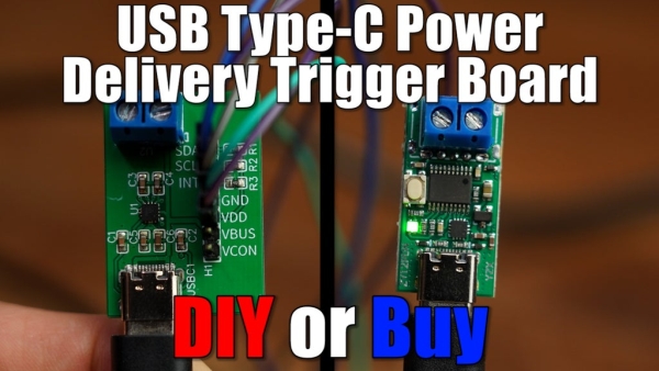
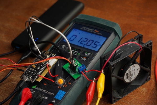
In this video we will have a closer look at a USB Type-C Power Delivery Trigger board. Such boards are used to output 5V, 9V, 12V, 15V or even 20V from a Power Delivery compatible power source. So I will be showing you how such a commercial board works and I will try to create my own DIY version of it in order to see whether it makes sense to DIY such a board or whether we should stick to the commercial solution instead. Let’s get started!
Step 1: Watch the Video!
Make sure to watch the video. It will give you all the information you need to create your own USB Type-C PD Trigger board. During the next steps though I will give you some additional information.
Step 2: Order Your Components!
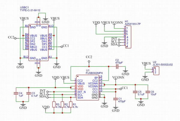
Here you can find the schematic for the project which shows you what components you will need for the PCB. You can order them here: https://lcsc.com/
Step 3: Get Your PCBs!
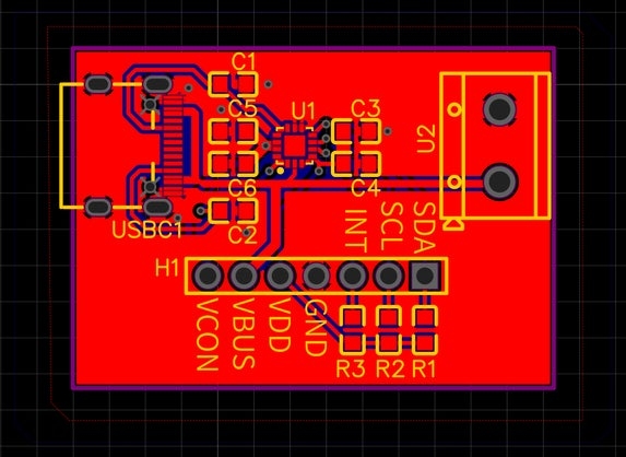
Here you can find the Gerber files for my PCB. Feel free to upload and order them here: https://jlcpcb.com/
Step 4: Do the Wiring and Upload the Code!
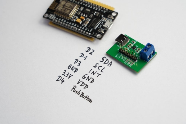
Here you can find the wiring diagram for the ESP8266 and the FUSB302 board along with the code provided by Reclaimer Labs.
Step 5: Success!
You did it! You just created your own USB Type-C PD Trigger board!
Feel free to check out my YouTube channel for more awesome projects:
http://www.youtube.com/user/greatscottlab
You can also follow me on Facebook and Twitter for news about upcoming projects and behind the scenes information:
https://www.facebook.com/greatscottlab
Source: DIY USB Type-C Power Delivery Trigger Board
- What voltage outputs can this board provide?
The board is used to output 5V, 9V, 12V, 15V or even 20V. - How do I get the schematic for the project?
The schematic is provided in Step 2 and components can be ordered via the linked LCSC page. - Where can I order the PCBs for this project?
You can upload the provided Gerber files to JLCPCB to order your PCBs. - What code should I use for the ESP8266?
The code provided by Reclaimer Labs is used for the ESP8266 and FUSB302 board. - Can I compare the DIY version with a commercial solution?
Yes, the video shows how a commercial board works and helps determine if creating your own makes sense. - Is watching the video required before starting?
Yes, you must watch the video to get all the information needed to create your own board.