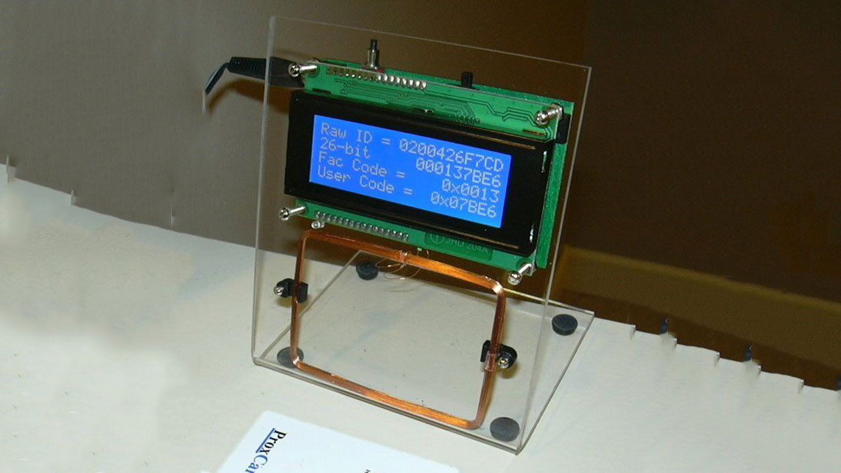
This page explains how to build an RFID reader with just an Arduino (Nano 3.0 was used in testing, but other models may be compatible), a wire coil made by hand, and various affordable common components.

Credits
The hardware and software designs for this project are based in part on the ideas, code and schematics posted by Micah Dowty here and Asher Glick here.
Background
RFID readers are devices sold by companies such as Parallax to read RFID tags with embedded identification circuits (we focus here on passive tags, activated by the reader’s transmitted RF energy). The design presented here shows how to wind a simple wire loop by hand (or create an equivalent printed circuit spiral version), connect it to an Arduino (or its chip), add a few low cost common components and create your own RFID reader. To make it more interesting (i.e. challenging), we will focus on the FSK class of RFID tags, which are fairly common among the 125kHz devices, but for some reason are not supported by the Parallax kits.
Micah Dowty has shown a design for an FSK/ASK RFID reader built around a Parallax Propeller device. His code, which is in assembly language, implements an ingenious (but complex) algorithm to create a dynamically variable analog bias voltage, which is used to pull the weak RFID signal into range, so it can be discriminated into binary signals by the Propeller’s digital input circuitry. He also dynamically tweaks the transmit/receive RF frequency to keep the antenna’s tank circuit in peak resonance for optimal signal to noise. There are three problems with his approach: first, the passive detection circuit lacks amplification, which makes it very sensitive to noise and therefore raises reliability issues. Second, the design is based on the Propeller chip, and if you are a fan of the Arduino and/or associated Atmel AVR chips, it leaves you out. And third, the dynamic slewing of frequencies and bias voltage is overly complicated, making it hard to debug. His general concept is attractive, however: use a microcontroller chip and wind your own wire loop to create, with some simple components and appropriate code, a complete DIY RFID reader.
Asher Glick has presented a solution for reading and decoding FSK RFID tags using the Arduino/AVR family (which he calls AVRFID), which is good except it apparently requires obtaining and modifying an existing Parallax RFID reader device (which natively only supports ASK).
Our goal here is to present a simple solution for reading FSK tags which addresses the above shortcomings: make it robust and reliable for real-world noise environments, base it on the Arduino, and build the RFID reader ourselves using a few simple low-cost parts, rather than buying and/or modifying one.
Circuit
Arduino DIY FSK-RFID circuit diagram:
The circuit diagram above was derived from the “World’s Simplest RFID Reader” design posted by Micah Dowty. Based on the Parallax Propeller, Micah’s approach was to use passive components only, without amplification, in order to achieve the ultimate in simplicity. The lack of amplification, however, results in a weak signal, potentially less than 2V PTP. This signal is then biased by an analog level produced by the Propeller, to try to maintain the signal’s DC level near the discrimination point of the Propeller’s binary-digital input circuitry. His code attempts to dynamically calculate that optimal midpoint level, and feed it into the circuit using a filtered PWM DAC output. Since the signal is weak, it can be distorted by interference and noise, with results in reduced reliability. The circuit presented here includes (as Micah suggests in his documentation) one active component: a common low-cost LM234 quad-opamp IC (or equivalent). This addition provides several significant advantages, at a negligible cost. First, the signal is amplified (using one of the four opamps on the IC package) to a more noise-immune level (of 2-3 volts PTP). Second, the DC level of the signal is maintained at exactly Vcc/2 using another opamp on the IC, which eliminates the need for the DC propping code in the Arduino. Third, having the signal amplifier in place allows another low-pass RC filter stage (another capacitor and resistor), which makes the final discriminated digital signal cleaner and more reliable. The end result is a more robust detected signal with improved noise immunity.
For more detail: DIY FSK RFID Reader using Arduino

