ESP8266 is an 802.11 b/g/n Wi-Fi module which became very popular recently because of its capabilities and ease of use and integration. Many electronics hobbyists are building projects on ESP8266 and they generally need to connect the module to a PC or a microcontroller. Some interfacing problems arise at this point.
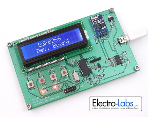
In this project, we are building an ESP8266 Development Board which lets the user make connection to ESP8266 from a PIC microcontroller and a PC. The board also provides all the needs to be used as microcontroller peripherals such as LCD display, pusbuttons, indicator LEDs and GPIO extension. The PC connection is done by the help of FT232RL USB-UART converter over a Mini-USB connector. Since the PIC microcontroller used is a 5V chip, 5V-3.3V bi-directional level converter circuits are also included on the board.
Circuit Design
The schematic of the project is drawn in SoloCapture, the schematic editor of SoloPCB tools. SoloCapture makes the schematic drawing process very easy and fast. You can download SoloPCB Designer tools at SoloPCB Designer for FREE.
You can download the SoloPCB design files of the project by using the link below.
For more Details: DIY ESP8266 Development Board