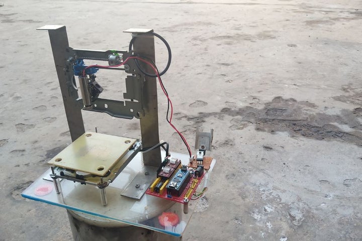
In this instructables I will show you how I made my own DIY laser engraver for very cheap. Also most of the parts are either salvaged from old things or are very cheap. This is a very interesting project for any electronics hobbyist. This engraver will be able to engrave wood, cardboard, vinyl stickers etc. and also for cutting paper due to the 250 mW laser that we will be using.
If this instructables helps you in any way in making your own laser engraver, do share your project with me. that’ll make me more than happy.
Step 1: Required Parts/ Materials and Tools
- 2x – Old DVD drives to salvage stepper motor mechanism.
- 1x – GRBL shield v4 ( can use other versions also).
- 2x – A4988 stepper motor drivers.
- 1x – 250 mw 650 nm laser with adjustable lens (from banggood.com)
- 12v 2-2.5 Amps power supply.
- Blank pcb for making laser driver circuit.
- Male and Female headers.
- 1x – 47 ohm resistor.
- 1x- 100k ohm resistor.
- 1x – IRFZ44N mosfet for the laser switching action.
- Some neodymium magnets.
- Acrylic sheet.
- M3 screws and nuts.
- Laser safety glasses.
- 1x – Arduino Nano.
TOOLS REQUIRED :
- Drill machine.
- Hot glue gun.
- Saw for cutting acrylic.
- File for finishing.
- Table vise.
- Screw driver Phillips head and flat head.
- Soldering iron.
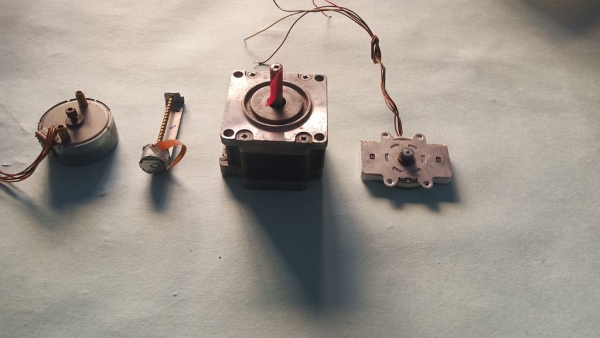
Step 2: Salvaging the Stepper Mechasnism and Neodymium Magnets.
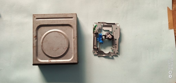
Two stepper mechanisms are required for the x and the y axis respectively which can be salvaged fromt be two used DVD drives. Salvaging the stepper mechanism and the neodymium magnets is rather easy. You can easily salvage it by opening up the cd driver using a Philips head screw driver.
Make sure you do not damage any parts related to the project while salvaging the required parts from the DVD drives.
If you are not familiar with hoe to do this, I’ll leave a link of a YouTube video that shows how to salvage the respective parts.
Step 3: Making the Base for the Machine.
For making the base I am using 4mm transparent acrylic sheet. The size of the acrylic sheet is 9in x 6.6in approximately.
Now we will have to create our stand for mounting the y axis with this acrylic base.
Leave 1in from the top and 1.5in from the side and place the stepper mechanism on the base. Now mark the respective holes and drill them in order to accumulate the y axis stepper mechanism.
These measurements are not that important. you can use your own space according to your needs.
Also I equipped this base with 4 silicon rubber pads so that the base stays firm on the ground or wherever its placed.
Step 4: Identifying Stepper Coil and Wiring.
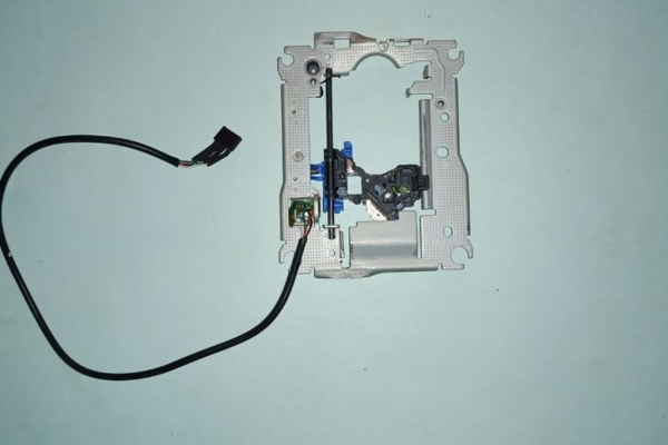
- The DVD stepper motors are bipolar stepper motors consisting of two coils and 4 wires.
- We need to identify the wires of the coil 1 and 2.
- For identifying the Stepper motor coil , we use a continuity tester which will show us a light of two wire are considering of the same coil.
- As per our grbl shield the are four male headers whose wiring is as follows.
1A 1B 2B 2A
- This shows that 1A & 1B are part of the coil 1 and 2A & 2B are part of the second coil.
NOTE – Images for each of the process are given so make sure you take a thorough look at it which will make it easier to understand.
Step 5: Making the Main Engraving Platform.
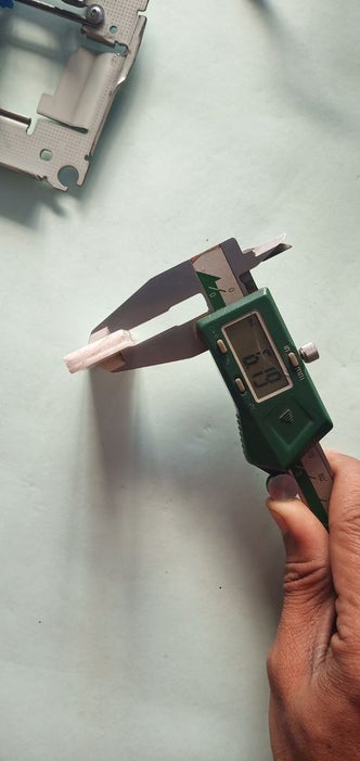
- For making the platform for engraving I am going to use some 2mm thin acrylic sheet pieces of size 40mmx22,5mm.
- I will be using tree similar pieces of the above size so that I could create a height of aboult 6 mm.
- Now attach the pieces together one by one on top of another by using some hot gluie.
- Once the whole thing is glued up it needs to be attached to the base of the stepper driver mechanism.
- This ensure that there is decent space between the stepper driver mechanism and the base platform that we will be installing.
- For man
Step 6: Making the Structure for the Y Axis.
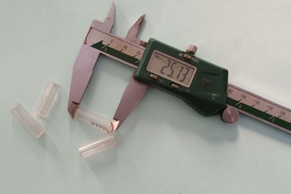
- For making the stand for the y axis and creating space between the mechanism and the base I used four spacers that I made by cutting a pen using an blade. The length of the pacers that we need is approx. 25mm which shall be sufficient for creating enough room in between the base and the mechanism.
- Now using m3 screws inserting them from below the acrylic base as shown in the image.
- Now by using some washers at both above and below the mechanism, secure the y axis stepper mechanism by using nuts
- Make sure that the screws are properly secured
Step 7: Making the Structure for the X Axis.
- After makong a study bas for the y axis, it’s now turn to make a mains for the X Axis.
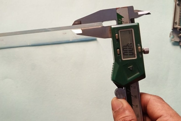
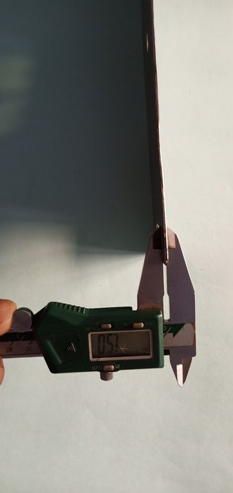
- For making the structure for the X Axis i am using sheet metal of 1.5 mm thickness. The material is stainless steel.
- You can get it in cheap from scrap.
- You can also use other materials like aluminium angles etc. its upto you whatever resources may be the best available to you.
- For making the stand we will require two prices from this steel sheet of width 30 mm each. So by using storable measuring device we will mark the lines.
- After this we will need to bend this at 90° at a distance of 80 mm for both the steel strips.
- Now all that is required is to cut these strips and bend it at 90°
- For cutting the strips you may require some tools so of you have a workshop that’ll be good else you can take help from someone that owns a workshop.
- After cutting make sure the steel sheet sides are properly finished making sure it doesn’t hurt anyone.
- For bending the strips you may catch the workpiece in a table vise and the by using a hammer you can bend it really at 90°
- Just check whether the bend is exactly 90°or not by using a set square.
- An improper bend will only increase your work so this process should be perfect.
Step 8: The Electronics.
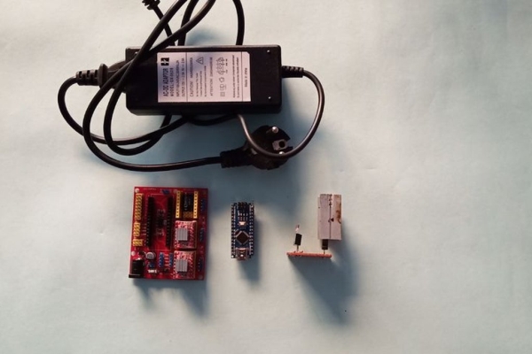
- Here comes the most important part of the project.
- For running the machine we will need a power supply of 12v 2 – 2.5 Amps.
- We need to setup the Arduino Nano and 2 A4988 drivers on the CNC GRBL shield v4 in the correct manner as shown in the image.
- If the alignment is improper and supply is given it may damage the stepper drivers or the microcontroller.
- After proper alignment of the drivers and the Nano we need to hook it up with the power supply and the pc and test whether the axis is moving in the respective direction or not.
- In my case when I tried the shield wasn’t responding to my commands from the laser GRBL software.
- Then I checked the connections on the shield with reference to the circuit diagram that I found on the internet.
NOTE – There was a manufacturing defect with my shield. For rectifying I tried the same thing with my friends shield and found that he too has the same problem. So I again soldered the step and direction pins of the A4988 of the X and the Y axis respectively.
- After soldering the step and directions pins again I was able to run the x and the y axis perfectly.
Step 9: Schematic for Laser Switching Circuit.
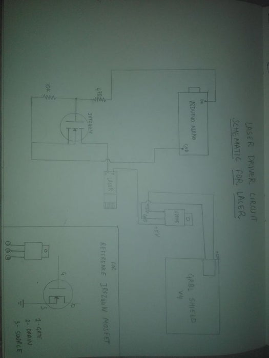
- The laser is switched by using an n channel mosfet Irfz44.
- The digital pin 11 of the arduino Nano is connected to the Gate of the mosfet by using the resistors shown in the schematics.
- The laser works with 5 volts so an LM7805 voltage regulator is used to provide the supply.
Step 10: Adding Rubber Feets to the Base.
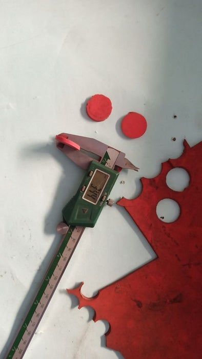
- For making the structure sturdy we need to add some rubber pads.
- For the rubber pads I am using a 3.5 mm thick sheet of silicon rubber and cutting four of the circular rubber pads of diameter 20mm.
- Now we need to attach these rubber pads to the base of our machine. For adhering this to the base we will be using synthetic rubber adhesive FEVIBOND.
- Adhesive should be attached on both the surfaces evenly. After apply the adhesive stick the rubber pad to the base an let it dry for at least 30 minutes.
- Adding these pads is not necessary but it shall help when the machine is placed on rough surfaces.
- Also this will protect the acrylic base from scratching.
Step 11: Stepper Motor Calibration and Steps/mm Calculation.
- For calibrating any machine that involves stepper motors require some calculations. These calculations are different for different stepper motors.
- So you need to calculate for your stepper motor.
- Steps/mm = Steps/Revolution * (micro stepping of the a4988)
- Steps/Revolution = 360/Step angle
- For my stepper motors, Steps/ Rev = 192
- Therefore, Step/mm = 192 * 1/16 = 12 Steps/mm.
- Now this values can be added in the grbl settings of the laser grbl software.
Step 12: Uploading GRBL Library and Setting Up Laser GRBL.
UPLOADING GRBL TO THE ARDUINO –
- For making this machine run we need to upload the grbl library to the Arduino .
- You can download the files from this link.
- https://github.com/grbl/grbl
- After downloading you need to extract the file.
- After extracting you need to place the folder in the following location- Program files->Arduino->Libraries. Paste it in this location.
- Now open the Arduino ide and connect the Arduino nano and select the correct port. Now include the grbl library and the upload it to the Arduino.
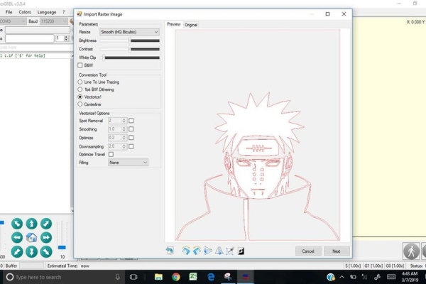
SETTING UP THE LASERGRBL SOFTWARE-
- Open the LASERGRBL software and connect the Arduino to the pc.
- Make sure you select the correct baud rate 11500.
- Now supply the circuit with the 12v 2.5 Amps. After giving the power supply both the stepper motors should be locked and should not be free.
- Now click on the connect button.
- Now Click on file>Open file>Select the file that you want to engrave>Click on OK.
- Now you ncan set the image as per your needs. In my case I am using vectorize the image and using none of the filling.
Source: DIY Cheap and Sturdy Laser Engraver.