Summary of DIY – Automated Garden Irrigation – (Arduino / IOT)
This article details building an automated garden irrigation controller using an Arduino Uno. The system monitors soil moisture, temperature, and humidity to activate a garden tap via a modified timer when conditions are dry but not freezing. Data is sent to ThingsBoard IoT for analytics, with alerts triggered for data loss or extreme soil conditions.
Parts used in the Garden Irrigation Controller:
- Garden irrigation poly pipe
- Jets
- Drippers
- Two dial electronic tap timer
- Tap pressure reducer 300kpa
- Arduino Uno
- Lora Arduino Shield
- Lora Gateway
- DHT11 Temperature Humidity sensor
- 5v Relay
- Telephone Cable
- Cable Ties
- Automotive Split Corrugated Tubing
- Automotive Terminal Connector Strips
- 2x Galvanised nails
- 1x Resistor
- Silicon / Caulk
- PVC Cement
- PVC Primer
- PVC Pipe 32mm width x 60mm length
- PVC Pipe 90mm width x 30cm length
- 3x PVC Push End Caps 90mm
- 1x PVC Screw End Cap 90mm
- 1x PVC Threaded Insert Fitting 90mm
- 1x PVC Push End Caps 32mm
- 1x 3.2V power source
- 1x 6-12V power source
- Thread seal tape
- Electrical tape
This project will show you how to build an irrigation controller for a home garden. Capable of measuring soil moisture readings and activating irrigation from a garden tap if the soil becomes too dry. The controller also includes a temperature and humidity sensor. The controller will not activate the garden tap if the temperature is too low. Sensor readings and statistics about water usage / run times are recorded on ThingsBoard IOT for visualisation and analytics. Alerts and emails are triggered if the irrigation controller stops transmitting data, the soil becomes too dry or too saturated.
Prerequisites
- Arduino knowledge including at least basic coding for Arduino and soldering.
- 1x pressurised garden tap
Bill Of Materials
- Garden irrigation poly pipe, jets, drippers etc.
- Two dial electronic tap timer ( ie: Aqua Systems Electronic Digital Tap Timer)
- Tap pressure reducer 300kpa
- Arduino Uno
- Lora Arduino Shield
- Lora Gateway (Not needed if you have a local Things Network gateway in range)
- DHT11 Temperature Humidity sensor
- 5v Relay
- Telephone Cable
- Cable Ties
- Automotive Split Corrugated Tubing
- Automotive Terminal Connector Strips
- 2x Galvanised nails
- 1x Resistor
- Silicon / Caulk
- PVC Cement
- PVC Primer
- PVC Pipe 32mm width x 60mm length
- PVC Pipe 90mm width x 30cm length
- 3x PVC Push End Caps 90mm
- 1x PVC Screw End Cap 90mm
- 1x PVC Threaded Insert Fitting 90mm
- 1x PVC Push End Caps 32mm
- 1x 3.2V power source (tap timer) [batteries, AC multivolt adapter]
- 1x 6-12V power source (arduino) [batteries, USB, USB to AC adapter]
- thread seal tape
- electrical tape
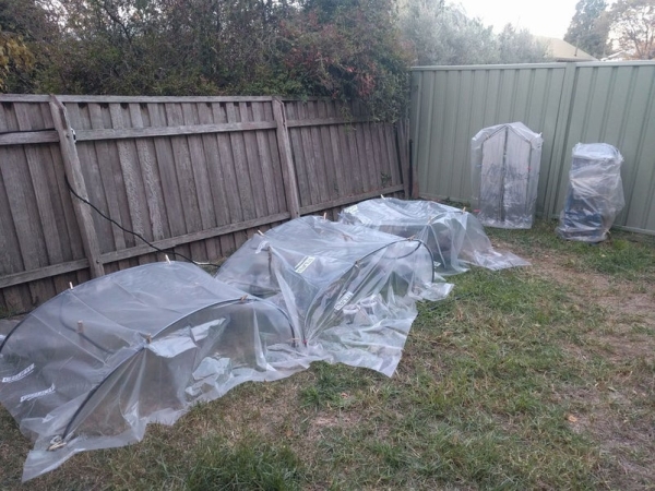
Step 1: Install Garden Irrigation
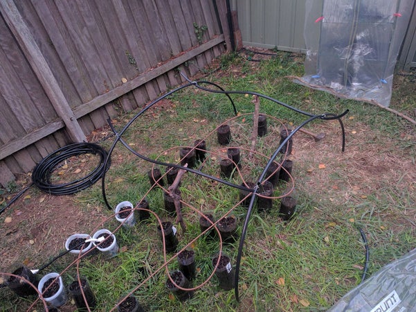
Layout poly pipe, fit jets, drip lines and drippers. The irrigation controller will work with any irrigation fit out. At it’s core it is measuring soil moisture readings and activating the tap timer if and when the soil is too dry. The controller can be calibrated to set the low point for saturation, how long the tap timer should be turned on for and how often the controller should check the saturation.
These settings can be changed on the arduino and stored in EPROM memory. The settings can also be updated by the IOT integration. This project will run the controller every four hours and turn on the tap for 3 minutes if the soil is too dry. It may run a few times in a row if dry/hot or once a day or two otherwise.
Step 2: Fit Tap Timer
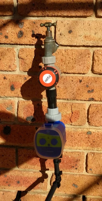
Fit the tap timer and experiment with the adjustable dials to work out a rough frequency and run time that works best for you irrigation installation. We will be removing the timer and modifying it to work with an Arduino.
Step 3: Arduino Build
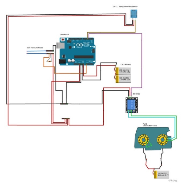
Use the wiring diagram as a guide for the build. In the photos telephone cable wiring has been used and screw terminal strips for junction points. Some soldering is required.
Tap Timer Modification
Carefully take apart the tap timer. We will be hard wiring the two adjustable dials so they can be controlled by the arduino instead of the manual dials. The left frequency dial will be hard wired to the reset position so that the right dial can be toggled between the on/off position. The right dial will have one wire coming from the centre right contact and the outer right contact as shown. By default the timer will be in the off position. If the two wires come into contact the timer will turn on. With the two wires connected to a 5V relay, an arduino can then close/open contact between the two wires. With one wire in the common relay terminal and the other in the normally closed terminal we will ensure that the timer is turned off when the arduino is turned off. Setting the relay pin to HIGH will turn on the timer; setting it to LOW will turn off the timer.
Soil Probe
For this project the two nails are soldered to wire connected to screw terminals. One nail’s terminal goes straight to ground. The other connects to an analog input in the arduino and a resistor. The resistor connects to the arduinos 5v signal. Shown in the wring diagram.
Temp/Humidity Sensor
The DHT11 Temp/Humidity Sensor is wired into the arduino’s 5V, ground and a digital pin on the arduino.
Lora shield
This project also used a Dragino Lora Shield (not shown in the wiring diagram).
PVC Base
The PVC Base for the arduino used in this project was designed so that the temp/humidity sensor could be exposed while keeping all other components secured inside the waterproof PVC enclosure. A small hole is drilled/cut for the sensor and silicon is used to hold it in place while stopping moisture from reaching the arduino. Shown in the diagram.
Step 4: Arduino Programming
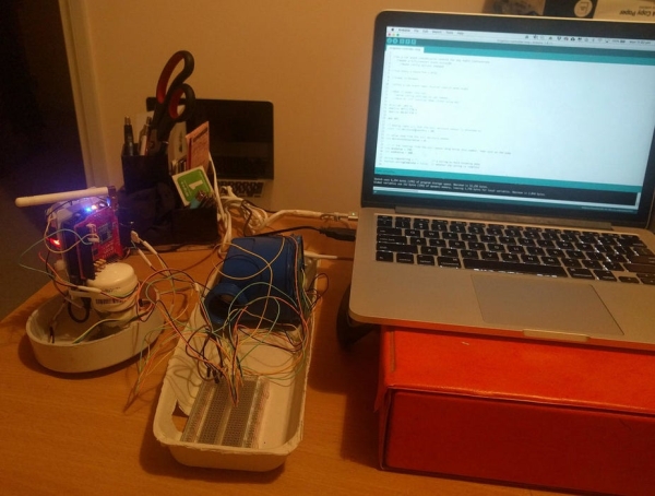
Connect the components together via a breadboard or terminal strips for programming and testing
EPROM Configuration
First we need to write configuration variables to EPROM memory. Run the following code on your arduino:
Here the DRY_VALUE is set at 960. 1024 means that the soil is completely dry, 0 means complete saturation, 960 was a good saturation level for the resistor, cable length and nails used. This may vary depending on your own configuration.
VALVE_OPEN is set at 180000 miliseconds (3 minutes). When/if the tap timer is turned on it will be left open for 3 minutes.
RUN_INTERVAL is set at 14400000 miliseconds (4 hours). This means that the controller will check the soil moisture every four hours and turn on the tap timer for 3 minutes if saturation is low (greater than 960).
The code above can be changed and these values modified at any time.
Program Code
Dependencies:
This example used the Dragino Lora shield and specifically the Lora concurrent example with the shield connecting directly to the Dragino Lora Gateway.
This can be adapted to use the Things Network by removing the code under the section “BEGIN: lora vars” and changing the program to include the following Dragino example or adapted to work with other radios/wifi shields etc.
The supplied code assumes that DHT11_PIN is digital pin 4, the RELAY_PIN is digital pin 3 and the soil moisture analog pin is analog input 0.
A debug variable can be set to true so that Serial debug messages can be logged at baudrate 9600.
Step 5: Enclosure Build
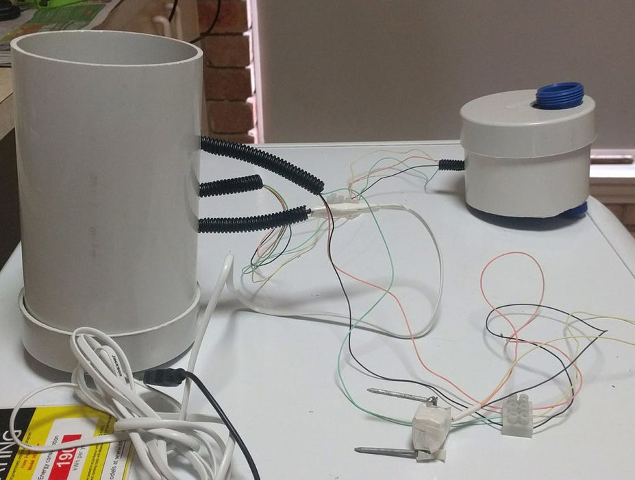
Cut the PVC pipe to suit the tap timer and Arduino base. Drill holes for the tap timer tap fitting and hose fitting. Drill holes in the pipe wide enough for the automotive conduit, slip 10cm lengths of the conduit into the holes and tease out wires from the arduino and tap timer. This should include:
From the Arduino
- Power supply wires and/or a usb cable from the arduino’s USB port.
- Soil Moisture cables (VCC,GND,A0)
- Two wires from the NC & Common screw terminals of the Relay
From the tap timer
- Power supply cables
- Two wires from the right dial contacts
Read more: DIY – Automated Garden Irrigation – (Arduino / IOT)
- How does the controller determine when to water?
The controller measures soil moisture readings and activates the tap timer if the soil becomes too dry based on calibrated saturation levels. - Can the controller operate in cold temperatures?
No, the controller will not activate the garden tap if the temperature is too low as monitored by the DHT11 sensor. - What platform is used for visualizing water usage statistics?
Sensor readings and statistics about water usage and run times are recorded on ThingsBoard IOT for visualization and analytics. - Does the project require a specific Lora Gateway?
A Lora Gateway is not needed if you have a local Things Network gateway within range. - How often does the controller check the soil moisture?
The default configuration runs the controller every four hours to check saturation levels. - What happens if the soil becomes too saturated?
Alerts and emails are triggered if the soil becomes too saturated or if the controller stops transmitting data. - How is the tap timer physically controlled by the Arduino?
The Arduino uses a 5V relay to close or open contacts between wires connected to the tap timer's right dial, turning it on or off. - Where should the temperature sensor be placed?
The temp/humidity sensor should be exposed outside the waterproof PVC enclosure while keeping other components secured inside.