Summary of The DIY Arduino Telescope GOTO control project
Summary: The author replaced a sluggish commercial motor kit by building an Arduino-based telescope control system using DC gear motors, encoders, an Arduino Mega, an encoder counter, and an L298 H-bridge. The Arduino handles motor control, tracking, GOTO calculations (using RTC and site longitude for sidereal time), safety checks, PEC, guiding, and sensors. An ASCOM driver on a PC provides application compatibility. The author does not publish full source code but offers guidance and partial code on request.
Parts used in the DIY Arduino Telescope GOTO control project:
- Arduino Mega 1280 (or Mega 2560)
- Maxon coreless DC motors with precious metal brushes
- 512 CPR encoders
- 30:1 reduction gearboxes
- Encoder counting integrated circuit
- L298 dual H-bridge motor driver
- DS1307 real time clock module
- Hall sensors (for homing/park alignment)
- Fuses and relays
- Power enclosure / housing for Arduino and electronics
- PC running ASCOM-compatible astronomy software and a custom ASCOM driver
Why make your own Arduino control system?
Once I finished building my homemade telescope mount, I installed a Meade DS motor kit to power it. This system was very sluggish, lacking in power, and untrustworthy. I couldn’t modify the programming or upkeep the system either. I chose to develop my own telescope control system from scratch and the Arduino platform appeared to be the most suitable option. This project required a variety of inputs and outputs, so it was completed using an Arduino Mega 1280 board, although a Mega 2560 board would work just as effectively.
DC motors or Stepper motors
Arduino and similar microcontrollers face a critical issue when it comes to stepper motors. Steppers need Arduino’s continuous monitoring to maintain their rotation. Particularly when utilizing microstepping. There isn’t much time left in the Arduino for doing other tasks. Although it may be typical to design this using multiple microcontrollers, it seems unnecessary when a single Arduino Mega provides more than enough computing power. So I decided to utilize DC motors.
Why ASCOM with Arduino
In a modern observatory, the PC is in charge despite the Arduino being capable of managing motor tasks and telescope pointing. A variety of astronomy applications are required for effective imaging. Every application communicates with telescopes through the widely used ASCOM interface. None of the software related to planetariums etc. that I wanted to utilize is compatible with my Arduino system: As a result, I had to develop an ASCOM driver to serve as a bridge between the Arduino and the necessary application software. Luckily, writing ASCOM Drivers is made simple due to their well-structured templates. This tool chain in action can be seen in the video below.
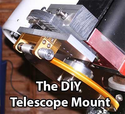
What is the hardware?
The core of the setup consists of two Maxon Motor coreless DC motors with precious metal brushes, 512 cpr encoders, and 30:1 reduction gearboxes. These motors are an impressive display of technology and can spin very gradually when controlled by Arduino without any magnetic cogging. The motors rotate at a speed of 12 rotations per minute while observing the sky.
This pairing produces an approximate resolution of 24 ticks per arc second when using the encoder IC at a 4x zoom level. This is sufficient for ensuring accurate tracking for both GOTO and tracking purposes. Nevertheless, it becomes an issue when slewing and the tick rate increases to approximately 200kHz. Attempting to utilize a encoder with an Arduino at elevated speeds results in various issues. In the case of overloaded interrupt lines, the serial data will be affected. It is recommended to use a specialized encoder counting integrated circuit for improved performance.
 Interfacing the motors to the arduino is a simple L298 dual H Bridge driver. The Encoders are interfaced to the Arduino using an encoder counting IC to cope with the very high tick rates when slewing.
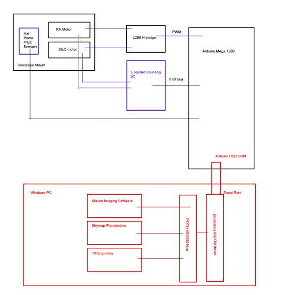
The diagram below roughly outlines the high level layout of the system
Please see here for discussion on Arduino PWM
The Arduino Mega 1280 is housed in a box on the telescope. This includes the L298 unit, the encoder counter, various hall sensors for doing PEC and fuses and relays. Arduino can actually turn off the power to the telescope mount itself – handy when you detect an problem.
What does my Arduino software actually do?
The Arduino is solely in charge of controlling the motors and aligning the telescope. While following the stars, the arduino watches the encoder tick rates and changes the PWM signal to the L298 in order to maintain the telescope’s alignment with the sky at the appropriate pace.
That task is quite straightforward. Complications emerge with the use of GOTO statements. When my planetarium software desires the scope to GOTO a target, it just informs the Arduino of the necessary RA and DEC.
At this stage, a variety of events occur on the Arduino.
- Initially, the Arduino checks with the DS1307 real time clock module to retrieve the current local time.
- Arduino utilizes the established longitude of the observatory in order to compute the local sidereal time.
- Understanding the specific RA of the target helps determine the necessary Hour angle.
- The necessary hour angle and declination are then utilized in order to determine the necessary shaft angles.
- Around 80000 encoder ticks are present per degree – therefore, we can determine the needed encoder tick target.
- The motors are instructed to move at maximum speed until they reach the desired number of encoder ticks, then gradually slow down and stop at the precise location.
In addition to this central function, a variety of other features are integrated into the Arduino.
- Putting away the telescope after use.
- Removing a parked vehicle
- Immediate closure due to urgent situation.
- Aligning the pointing with a familiar star.
- Correction of the periodic errors in the transmission gears is known as Periodic error correction (PEC).
- Automated guiding
- Temperature and humidity are being monitored locally.
- Locating a housing alignment (utilizing Hall sensors)
A variety of safety checks are coded to detect any potential issues that may occur. If the slew takes too long or the telescope moves too slowly, the Arduino will cut off power to the mount and enter sulk mode. The power will not be restored until a person has fixed the error.
Can I download your Arduino source code?
In short, no. The code is closely matched to my telescope and has taken me months of research and development. It is not impossible that this may turn into a commercial project one day therefore I do not wish to share my entire source code.
However, I would be delighted to answer questions about the project at [email protected] and will happily share a section of the code if it helps you with your project.
However, I do give instructions on how to write it yourself here in my guide for writing Arduino telescope controllers
Source: The DIY Arduino Telescope GOTO control project
- Why choose Arduino for the telescope control system?
The Arduino Mega offers sufficient I/O and processing power for the various inputs and outputs required, avoiding the need for multiple microcontrollers. - Why use DC motors instead of stepper motors?
Steppers require continuous monitoring by the Arduino, leaving little time for other tasks; DC motors avoid that constraint. - How does the PC communicate with the Arduino telescope controller?
Through an ASCOM driver written as a bridge between the Arduino and astronomy applications. - What motor hardware is used for precise tracking?
Maxon coreless DC motors with 512 CPR encoders and 30:1 gearboxes are used for smooth, low-speed tracking. - How are high encoder tick rates handled during slewing?
An encoder counting integrated circuit is used to cope with the very high tick rates when slewing, offloading counting from the Arduino. - What motor driver is used to interface motors to the Arduino?
An L298 dual H-bridge driver interfaces the DC motors to the Arduino. - What tasks does the Arduino perform for a GOTO command?
It reads the RTC, computes local sidereal time from longitude, derives hour angle and shaft angles from target RA/DEC, converts to encoder tick targets, then slews and fine-controls motors to the target. - Does the Arduino include safety features?
Yes; it monitors slew timing and speed, can cut power and enter sulk mode on errors, and requires human intervention to restore power. - Is the Arduino source code available for download?
No; the author does not publish the full code but will answer questions and may share code snippets on request. - What additional features are implemented on the Arduino?
Features include parking, unparking, immediate closure, star alignment, PEC, automated guiding, temperature and humidity monitoring, and housing alignment via Hall sensors.