Summary of DIY Arduino Motor Shield
This project builds a low-cost Arduino motor shield using an L298N driver (vertical package), controlled by four PWM pins, with fast recovery diodes for rapid braking—suitable for SUMOBOT competition. The guide includes datasheet, schematic, PCB layout, Arduino test files, and six-step instructions. Specs: 5–50 V, 2–4 A, up to 25 W, Arduino Uno compatible, two motor outputs, PWM on pins 11/10 and 6/5. PCB artwork created in Fritzing; parts can be sourced locally or substituted as noted.
Parts used in the Arduino motor shield (driver):
- L298N Motor Driver Chip
- 7806 Regulator Chip (substitute: 7805–7809)
- 1N4937 Fast Recovery Diode (substitute: 1N4007 or 4148)
- 1 Ohm 1/4 watt Resistor (substitute: up to 10 Ohms)
- Screw Terminal Blocks
- PCB Board (Regular or Photo-positive)
- Male or Female Pins (for Arduino connection)
- Heatsink (bought or DIY)
Today, I’m going to show you how to make an Arduino motor shield (driver) at a low cost. It works splendidly, its posses almost all the characteristics of the original Arduino motor shield. It’s almost considered as a clone. The original Arduino motor shield has the same motor driver chip (L298), the only difference with it, is the package type, my project contains the vertical version of the chip L298 (with a “N”).
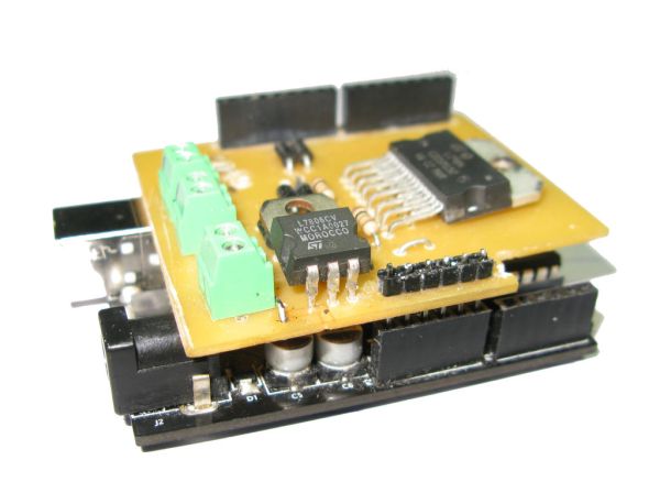
Structure:
It’s controlled using 4 PWM pins. The connections are: 11&10 for the R-Motor and 6&5 for the L-Motor. With the help of eight fast recovery diodes (1N4937) it shows a very fast response of stopping/ braking, that’s why I’m going to use it for the national SUMOBOT competition.
What Is A Motor Shield?
A motor shield is a circuit that drives different loads such as motors, lights and etc… The Arduino Board (Microcontroller) itself isn’t designed to operate high current loads, that’s why we use motor shields, it is a circuit that is controlled by your arduino board to drive high power accessories.
Cost:
It only cost me P363.75 (Converted: $8.87)! The prices would decrease to P262.50 (Converted: $6.40) if I sticked to the original plan, since it’s for competitional purposes, I substituted some parts with a higher rate of response.
About The Guide:
The guide includes the datasheet, schematic diagram, PCB layout, Arduino test files and etc…. All you need is an hour and the 6 step instructable.
Specs:
____________________________________________________
Voltage Range: 5- 50 volts
Current Range: 2-4 Amperes
Power: 25w @75°C
Working Temparature: -40°C to 150°C
Board Compatibility: Arduino Uno
Motor Outputs: 2 Motors (Left & Right)
Possible Robot Movements: Left, Right, Forward, Backward & etc..
PWM Pins: [12&11] [6&5]
The PCB layout is my original design, it was created using Fritzing Software, please ask for permission if anyone is willing to modify and republish it.
Step 1: Parts & Materials
I bought my parts in ALEXAN, a local electronic store with tons of branches (Only Found In The Philippines). Everything is cheap there, the links that I gave is only an alternative for online purchases. My real price list and spending is a lot different and cheaper. If you live in the Philippines, you can buy in DEECO, Alexan, E-Gizmo or Raon.
Parts:
– L298N Motor Driver Chip
– 7806 Regulator Chip
– 1N4937 Fast Recovery Diode
– 1 Ohm ¼ watt Resistor
– Screw Terminal Blocks
– PCB Board (Regular or Photo-positive)
– Male or Female Pins (Used to connect to Arduino)
– Heatsink (Bought or DIY)
7806 Regulator Chip = (Substitute: 7805- 7809)
1 Ohm ¼ watt Resistor = (Substitute: Up to 10 Ohms)
1N4937 Fast Recovery Diode = (Substitute: 1N4007 or 4148)
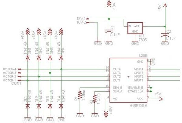
Step 2: PCB Making
In this step, I will show you the schematic diagrams, datasheets and PCB layouts. Just download the files below. If you don’t know how to make a PCB, please visit my other instructable guide “DIY Customized Circuit Board (PCB Making)“. I used a Photo-postive PCB board instead of the traditional toner transfer. The photo-postive PCB is a bit rare in the U.S. that’s why some should stick with the toner transfer method. Also don’t forget to drill holes on them :)))
In making the photo-positive PCB, it’s better to stay in a dark area and have a 10W fluorescent lamp beside you, also use a kitchen timer to set a 5 minute alarm for counting the exposure time.
 L298N Datasheet.pdf599 KB
– 7806 Regulator Chip
– 1N4937 Fast Recovery Diode
– 1 Ohm ¼ watt Resistor
– Screw Terminal Blocks
– PCB Board (Regular or Photo-positive)
– Male or Female Pins (Used to connect to Arduino)
– Heatsink (Bought or DIY)7806 Regulator Chip = (Substitute: 7805- 7809)
1 Ohm ¼ watt Resistor = (Substitute: Up to 10 Ohms)
1N4937 Fast Recovery Diode = (Substitute: 1N4007 or 4148)
- What motor driver chip does this shield use?
It uses the L298N motor driver chip in the vertical package version. - Which Arduino pins control the motors?
It is controlled using four PWM pins: 11 and 10 for the right motor, and 6 and 5 for the left motor (also listed as 12 and 11 and 6 and 5 in specs). - What diodes are used for fast braking?
Eight 1N4937 fast recovery diodes are used for rapid stopping and braking response. - What are the voltage and current ranges of the shield?
The voltage range is 5 to 50 volts and the current range is 2 to 4 amperes. - Is the shield compatible with Arduino Uno?
Yes, the board is compatible with Arduino Uno. - How many motors can this shield drive?
It can drive two motors (left and right). - What resources does the guide include?
The guide includes the datasheet, schematic diagram, PCB layout, Arduino test files, and a six-step instructable. - What is the approximate cost of the project?
The project cost about P363.75 (approximately $8.87) and could be reduced to P262.50 (about $6.40) following the original plan. - What PCB design tool was used for the PCB layout?
The PCB layout was created using Fritzing software.