I study Game and Interaction technology at Utrecht University of the Arts. There is one project called “If this then that” where you’re asked to build an interactive product. You are to use an Arduino, design an interesting interactive element and build a nice and professional-looking prototype around it. I had some clear personal wants going into this project: I wanted to learn how to weld, I wanted to learn to program in C/C++ and I wanted to drive a 14-segment display that had been lying around my place forever. It took me a couple of weeks to come up with an idea that tied these together but then finally it came to me: I was going to make a chest that you need to open with a code, but not any code. A pressure sensor is continuously read and shown on a display, you have to reach the right number and confirm it three times to unlock the chest.
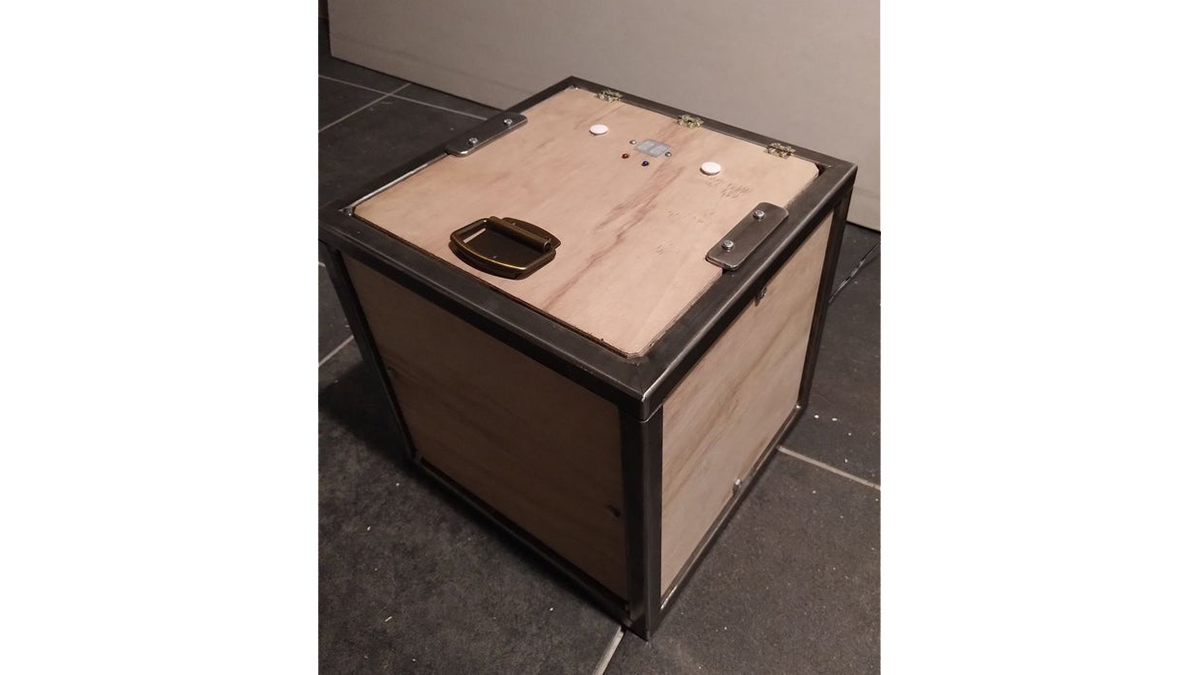
I wanted the chest to have a kind of modern-industrial look so my material choice were steel and wood.
In the end I’m quite happy with how it turned how! I wrote the steps out below so you can recreate or even improve it! Have fun!
Step 1: Gathering Ingredients
Before we begin, we’ll need some parts. Here is the full list:
Casing:
- 350cm square steel tube, 20x20x2mm
- 6x 26x26x0.9cm plywood panels (the most efficient way is the cut a board that is larger than 52x72cm in six pieces, but make sure you have some leftover wood!)
- 1x 26x22x0.9cm plywood panel
- 90cm 22x30mm wood (cut in pieces of 26cm, 2x 18cm and 2x 12cm)
- Small hinges
- 2x chord loops
- Screws: 4.0×16, 4.0×20, 4.0×25, 3.0×12 (around ten of each, including some spare)
- Bolts: M3x20, M6x12, 1x M10x30 (around ten of each, including some spare)
- Nuts: M3, M6, M10
- Handle
- 2x 8cm 25x4mm steel bars
Electronics:
- Button
- LED red
- LED blue
- Force sensitive resistor
- Lock-style solenoid (mine is a 12V 650mA model)
- HDSP-A22C 14-segment display
- MCP23017 Digital I/O expander
- 15x resistor 470
- 3x resistor 1k
- 6x resistor 10k
- 1N4007 diode
- 2x BC547B transistor
- 2x BC557B transistor
- TIP31A transistor
- 12V 1A wall adapter
Step 2: Building a Chest – the Steel Frame
The chest is a 30cm large cube, made of steel tubing and wooden panels. In the garage I found nice square tubes of 20x20mm with 2mm thick walls. The walls need to be thick enough to weld and to tap threaded holes for M3 bolts. 2mm is the perfect thickness for this. Of course you can use any kind of steel tubing for this if you have any better ideas.
The most elegant way to build the frame is to make two squares of 30x30cm and then connect these two squares using 26cm (30 – 2*2) tubes. To make the squares, cut the long steel tubes diagonally into eight pieces. The ends of the pieces should be cut at an angle of 45 degrees facing towards each other. The long ends of the piece is 30cm. When using a mounted saw, it’s easy to rotate the blade at 45 degrees and turn the tube after each piece. This wastes the least material. After you have the eight diagonally-cut pieces it’s time to cut four more straight ones. These pieces are 26cm in length.
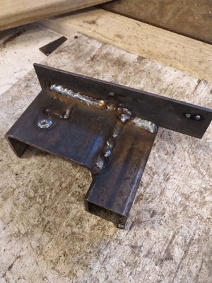
Then finally cut ten pieces of around 6cm of a 20x4mm steel bar. These will be the mounting points for the wooden panels.
When all the metal is ready, it’s time to weld. The toughest part here is lining out the tubes you have cut. Let’s start with the top and bottom squares. Take the diagonal pieces and line them out in a square on a piece of wood. A tip here is to use a roughly square plate of about 30cm so you can let the corners fall of the edges if you lay them out at a 45 degree angle compared to the wood. Fasten them with some clamps and make sure the metal touches in all corners so the electricity can flow from each piece to the next while welding. If you’ve never welded before, now is the time to practice a bit because if you mess it up, you can do everything so far over. Anyway, weld the pieces together in the corners (I chose to do it on the inside) and you have now completed the first part! The second square is easier to line out as you can just lay it on top of the first one. Weld these together as well. If everything went right, you should now have two identical steel squares.
At this point you’re gonna want to attach the mounting points for the wood. I used two pieces for each panel on the opposing edges of the cube. I chose a specific pattern so no piece wouldn’t get in the way of the lid and so I wouldn’t have to mount two pieces on the same edge. You can do it any way you like, as long as the edge where the solenoid will be locked at doesn’t have one.
At this point I also took a grinding tool with a steel brush attached to clean the steel. The bars had some rusty spots on it and I found it gave them a nice look.
To finish building the steel frame we only need to connect the two squares we have now. The easiest way is to place them upright on a level surface and lay two of the 26cm tubes between them. An extra pair of hands will come in very useful when you’re clamping them down. Weld this together and repeat it for the other side.
If everything went right, the steel frame should be done by now!
Step 3: Building a Chest – the Sides and the Lid
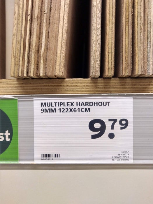
To finish the chest, we need to add wooden paneling to the sides. keep in mind that the electronics will be hidden in the lid, so you’re gonna need a little bit more plate than just 6 pieces of 26x26cm. At the DIY store they had 122x61cm, which was perfect. I chose a bit thinner wood than I originally intended but it ended up looking better than thicker wood would’ve. When the steel tube is 2cm wide, has rounded corners and the mount is 4mm wide, you’ll be left with some 10mm for the panel while still keeping a good look. The plates I found were 9mm thick so that was perfect.
Cut the plates into six panels of 26x26cm. If your weld are a bit big you will need to cut off the corners. When you have the plates, lay them out into the frame. It’s convenient to label which one goes where. In the middle of the wood, mark the place where the two holes will be. Place the wood in the frame at its respective place and drill the hole for the bolt. I had M6 bolts lying around but any bolt is good. Bigger bolts might give it a bolder look, but even an M3 can hold it together just fine. Do make sure the bolts are not too long, as they will protrude into the frame. This is where you will put your things so when there are long bolts sticking out, it’s going to be a little inconvenient. If you used the exact same material dimensions as me, a 20mm bolt should be what you’re aiming at. When the holes are drilled you can mount the plates but make sure to wait with fastening anything before the lid is finished, you’re not gonna want to lock yourself out!
For the lid, we start with one of the plates we cut for the sides. The idea is to make the lid into a case for the electronics. At the DIY store I also found a 22x30mm piece of wood, which would make the perfect distancer. It provides three centimeter where you can hide your electrics. Before gluing these on the lid, we need to make holes in the wood. They are all round holes except the one for the display. For the round ones, use a drill. For size reference, use the schematic in the images above. For the display you can use either an electric jigsaw or a milling machine if you want to be more precise. Once all the holes are cut and drilled, you can glue the pieces of wood on the sides of the panel, in upright position! Also be careful that your solenoid still fits in the space that’s left over. When it’s all glued, take the exact measurements and cut one more panel of wood to these dimensions. You’ll already want to screw it on the bottom of the wooden spacers so you can cut the corners flush with the corner of the panel you started with.
Now we need to make the buttons for the pressure sensor and the action button. We want to hide the actual button from the user so we’ll mount them under the lid, inside the electronics compartment. I simply cut a couple of small pieces of wood from the leftover plywood to serve as spacers. Solder the push-button onto a PCB and screw it on the pieces of wood that are glued to the underside of the lid, making sure the button comes out exactly in the center of the hole. The pressure sensor is a bit different. For this, use two spacer pieces glued to the lid as well but take a third piece to make a bridge over the hole. Glue the sensor exactly in the center of the hole.
To control the buttons through the lid, it would be ideal to 3d-print something. Unfortunately I didn’t have time for this so I improvised. You can do whatever you want, but a tip here is that you need something to block the button from falling out on both sides. I used shortened bolts with a nut cut in half on one end end and I covered it up with something I found lying around.
The next thing to mount is the solenoid. Every solenoid is slightly different but the easiest way to mount most solenoids is to layer wood between the brick and the lid until it exactly slips behind the frame, but also far enough back to not touch the wood when it is extended. For me this was 6mm. I then had to grind away some steel later again because in the end it still wasn’t far enough down. I should probably have had about 7 or 8mm.
The lid is now mostly done and only the electronics need to be added. This is the right moment to first attach the lid to the frame. Try to get some small hinges at a local store, these should not be bigger than the steel tubing (~18mm)! Depending on the size and quality of these hinges, you can use either two or three. Mark their position on the frame and on the lid. Now get an extra pair of hands that will hold the lid in place while you mark where to drill holes. The holes in the steel tube should be threaded so you can just screw in a bolt without having to worry about how to fasten it. When the hinges are attached to the frame, get back those extra hands and screw the lid on the hinges using some small screws. Because you need to work on the lid later again you can wait with this step as well until everything is done.
Now, we’re ready to work on the electronics!
Source: Digital Treasure Chest