Summary of Music Box With Mini Monitor(OLED) and LED
This project is an interactive wooden music box that acts like a small robot. It plays music when opened, displays emojis on an OLED screen to show emotion, and features an LED that lights up if the user squeezes a force-sensitive resistor during the song loop. The music stops immediately when the lid closes, pressing a button.
Parts used in the Music Box With Mini Monitor(OLED) and LED:
- Arduino Uno
- 0.96 OLED I2C display
- Piezo buzzer
- Pushbutton
- Force-sensitive resistor
- LED
- 220 Ohm resistor
- 1KOhm resistor
- Jump start cables
- Small circuit board
- Soldering iron and tin
- Wood plates
- Saw
- Sandpaper or sanding machine
- Hammer and nails
- Hinges, screws, and a small latch
- Drill and screwdriver
- Duct tape
My idea was a box that would play music when you open it. It also has a display with an emoji on it that awakes, greeting you. There is also a LED in it that lights up if you hold the Force-sensitive resistor squeezed between your fingers, while the next loop of the song happens. The music stops if you close the box again because the lid presses closed on a button.
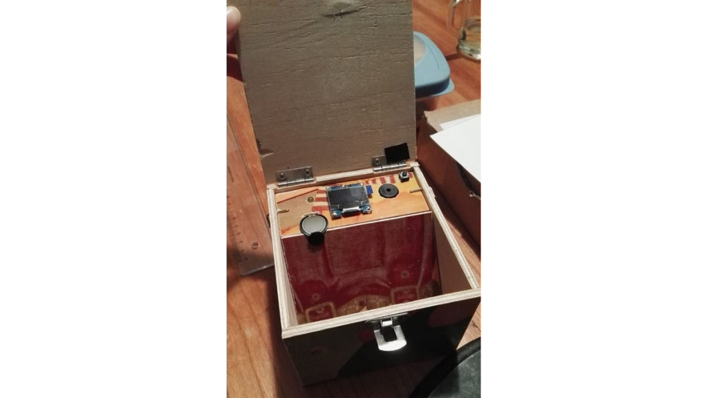
I wanted to make a box that next to being a music box also felt kind of like a little robot with personality. The display that shows 2 emojis plays the biggest role in this, because I noticed people relate more with objects that have a face. The emojis on the display express emotion, which contributes to the idea of it being a small robot. I noticed people react to this positively. The force-sensitive resistor adds interaction to it. If you hold it pressed just as the song goes on to the second loop, a light will go on which is a sign the box reacts to you. The light I chose is yellow which is a happy color and matches the exterior of the box.
Here follows a walkthrough on how I made this project.
Step 1: How I Started, and What You’ll Need.
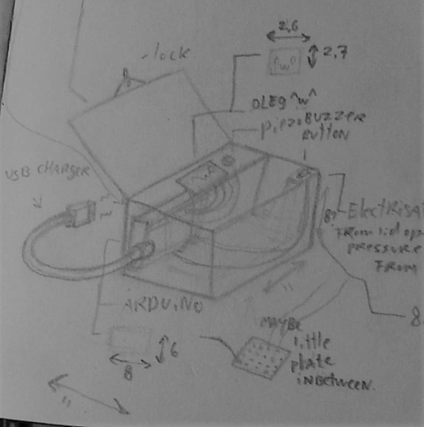
I started by making a concept sketch of what I wanted to make.
What you’ll need:
1. An Arduino. (I used an Arduino Uno.)
2. An OLED display. ( I used a 0.96 OLED I2C)
3. A Piezo buzzer.
4. A Pushbutton.
5. A Force-sensitive resistor.
6. A LED.
7. A 220 Ohm resistor and a 1KOhm resistor.
8. Wires. (I used jump start cables.)
9. A small circuit board.
10. A soldering iron and tin.
What you’ll need to make the box:
1. Wood.
2. A Saw.
3. Sandpaper or a sanding machine.
4. Hammer and nails.
5. Hindges, screws and a small latch.
7. A drill and screwdriver
8. duct tape.
A full version of the code of the entire project will be included later on in this tutorial.
Step 2: Compose a Song.

Next, I composed a song I wanted the box to play.
I used a digital software for this, but you can also use an instrument and write down the notes, or play around with your Piezo buzzer and frequencies.
It’s very easy to hook up a piezo buzzer. All it needs is an input pin.( I used 12) and a ground pin. I also placed a button in between the 2 sides of my breadboard to act as a bridge. This button will stop the sound if pressed,
I used this handy site to translate the notes into frequencies for my code:
http://pages.mtu.edu/~suits/notefreqs.html
In the third picture, you can see a little piece of my code for the song. After ‘tone’, the first digit between the parentheses is de pin where the Piezo buzzer is connected to. The second digit is the frequency of the tone. With delay, the number between the parentheses is how long the tone holds on until it goes to the next one underneath it.
Step 3: Connect the OLED.
The OLED I used has four points: GND, VCC, SCL and a SDA.
GND you connect to the GND (ground) on your Arduino.
VCC you connect to the 5V (5-volt) on the Arduino.
SCL to SCL.
And SDA TO SDA.
To make the OLED work you first have to download some Libraries.
I downloaded the Adafruit Circuit playground, Adafruit GFX Library and the Adafruit SSD1306.
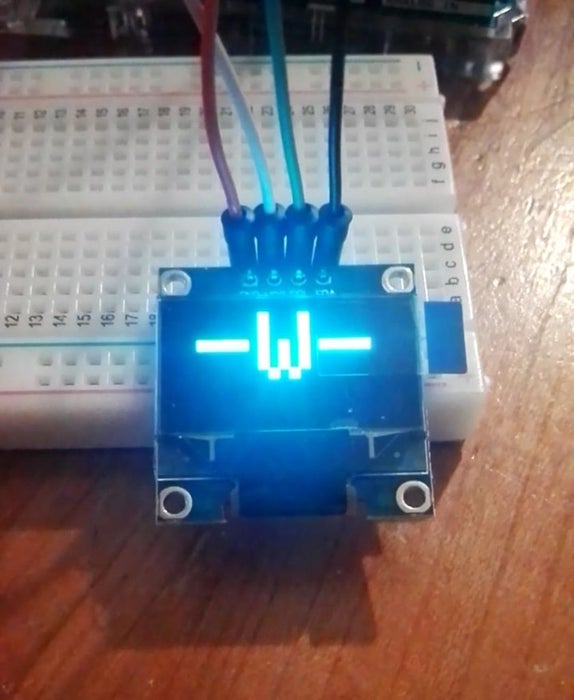
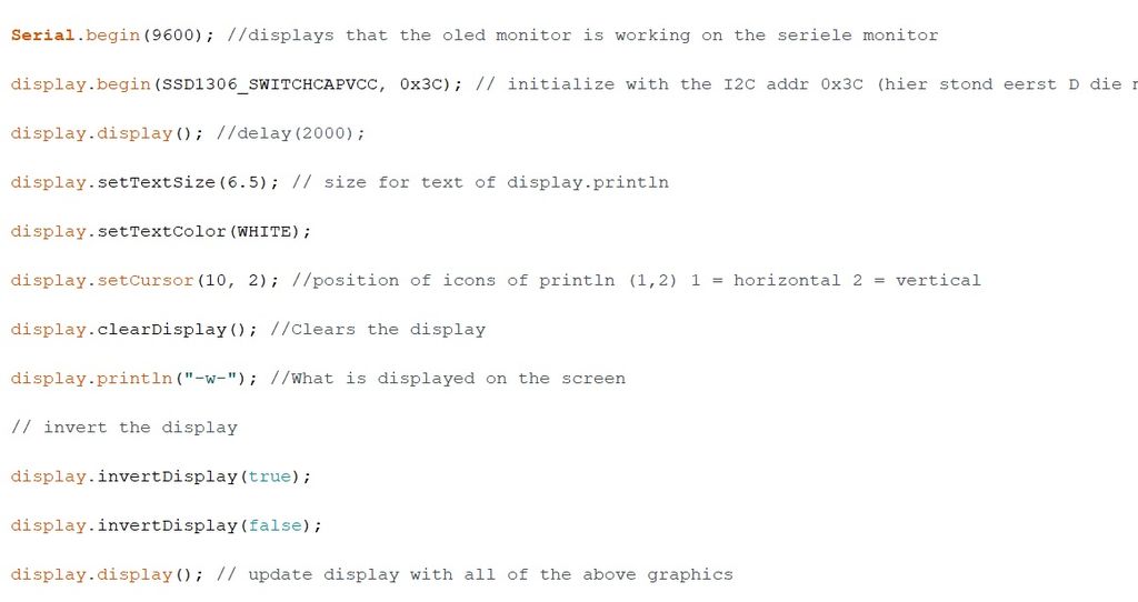
I used the example sketch ssd1306_12x64_i2c to see if it worked. You can find this at File> example> Adafruit SSD1306> ssd1306_128x64_i2c (I chose this one because my screen has this size) You can see this in the second picture
If this file doesn’t work it could be that you need to change something small in it.
Look in the code under the void setup for:
if(!display.begin(SSD1306_SWITCHCAPVCC, 0x3D)) { // Address 0x3D for 128×64
I bolted the D here because I had to change this D into a C to make it work.
In the third picture, you can see a bit of my code that makes the emoji of the first picture.
Step 4: Connecting the Force-sensitive Resistor and LED to the Rest.
To connect the Force-sensitive resistor and the LED you need 2 resistors. The 220 Ohm for the LED and the 1K Ohm resistor for the Force-sensitive resistor.
LED:
The positive leg of The LED needs to be connected to a 220 Ohm resistor which connects to pin 10 on the Arduino. The negative leg of the LED needs to be connected to the ground line on a separate little circuit board. On the circuit board I made a ground line and a 5-volt line, because I had too many pins that needed to go there and not enough holes on my Arduino.
Force-sensitive resistor:
The Force-sensitive resistor needs the left leg to be connected to both a 1K Ohm resistor, and a wire which connect to hole A0 on the Arduino. The 1K Ohm resistor Connect to the ground line on the circuit board.
The right leg you connect to the 5-volt line on the circuit board.
To make this all work in the code you need to define to what pin it is connected to above the void setup(){.
Step 5: The Code.
Here follows a link to the code:
https://github.com/kai-calis/Kai-fawn/blob/master/Arduino%20code%20for%20a%20school%20project
Step 6: Building the Box.

You saw out 8 wood plates in total.
The wood I used is about 0.5cm thick.
1. The lid and bottom of the box are 11cm by 11cm.
2. These are the left and right side of the box which are 10.2cm by 8cm. Make one of the plates with a square hole for the USB cord of the Arduino to stick out. This hole is 1.5cm by 1.5cm and is about 1 centimeter from the start of the wood plate.
3. These are the front and back of the box, and is 11cm by 8cm
4. This is the little shelf the Piezo buzzer, OLED and the rest will rest in. You will have to drill a hole for the OLED of about 1cm by 0.5cm so the wires can stick out, but the rest of the OLED can rest on the shelf.
For the hole of the LED you need a drill bit of 0.5cm.
For the Force-sensitive resistor, you need a hole of 1cm by 0.5cm
For the Piezo buzzer, you need a hole of 1.4cm.
FOR the Push button you need 4 small holes of 0.2cm so its legs can stick out.
5. Lastly, you’ll need a wood plate of 10cm by 10cm, this plate will cover the Arduino and its wires. I shaved and filed down two of the opposite sides of this plate to make it able to lean on the shelf of number 4 and to lean snugly in the corner of the box.
I used nails to connect the sides, 2 hinges for the lid and a lock to keep the lid closed.
Don’t forget to file all the edges to get a cleaner look and avoid splinters.
While building the box don’t put number 4 and 5 in just yet!
Step 7: Time to Solder.
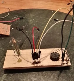
I included a wire map so you can copy it from the picture.
Don’t forget to test if things are connected correctly by seeing if it works in between soldering.
After soldering I hammered in 2 small nails to keep the OLED from shifting.
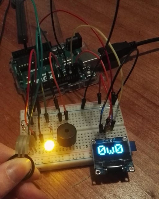
In the end, it should look something like the third picture.
Step 8: Putting It All Together.
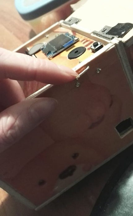
To put the shelf of number 4 from the previous step in there, I first measured how hight it needed to be to be pressed by the lid. You can do this by measure how high the button sticks out from the shelf and how high it is when pressed in. This length you add to the thickness of the wood you used and put two nails there on each side. The shelf will rest on those. I added 2 extra nails, one on each side, above the shelf to keep them in place. I bend those nails like an L shape so I could easily use that hook to remove them again.
Removing the Shelf, I connected wood plate number 5 to the shelf of number 4 by sticking a piece of duct tape under number 4 and sticking the extended end under number 5. You should have something like picture 3.
Unfortunately, I hadn’t anticipated the hinge to be leaning just on the rim of the push button, preventing it from pushing in the button. A quick solution I found was putting a thin piece of plastic, about the same thickness of the hinge, right above it so it would press down on the button.
Source: Music Box With Mini Monitor(OLED) and LED
- How do I stop the music from playing?
The music stops when you close the box again because the lid presses closed on a pushbutton. - What components are needed to make the box?
You need wood, a saw, sandpaper, a hammer, nails, hinges, screws, a latch, a drill, a screwdriver, and duct tape. - How does the Force-sensitive resistor work in this project?
If you hold it pressed just as the song goes on to the second loop, a light will go on which is a sign the box reacts to you. - Which Arduino library files did the author download for the OLED?
The author downloaded Adafruit Circuit playground, Adafruit GFX Library, and Adafruit SSD1306. - What color is the LED chosen for the project?
The light chosen is yellow, which is described as a happy color matching the exterior of the box. - How do I connect the OLED display to the Arduino?
GND connects to GND, VCC to 5V, SCL to SCL, and SDA to SDA. - What dimensions should the lid and bottom of the box be?
The lid and bottom of the box are 11cm by 11cm. - How can I translate musical notes into frequencies for the code?
You can use the site http://pages.mtu.edu/~suits/notefreqs.html to translate the notes into frequencies.