Summary of Cyborg Hand : Robotic-cum-Prosthetic Servo Powered Hand
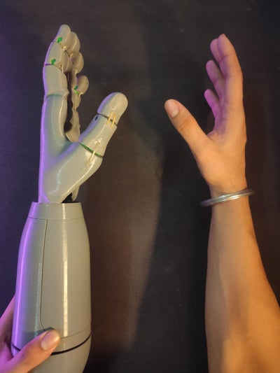
This project builds a 3D-printed robotic-cum-prosthetic hand using PLA and TPU parts, five MG995 servos, an Arduino, and a string-pulley actuation with rubber-band return. Designed in TinkerCad and Fusion360, the hand mimics natural finger motion (three phalanges per finger), supports wrist rotation, and can be controlled via potentiometers, EMG sensors, gloves, or code. Print files, G-code, assembly steps, wiring guidance, and Arduino code are provided. Final dimensions: 42 cm length, 10.5 cm width, 580 g weight; gripping strength ~8 kg, usable lift ~1.5–2 kg.
Parts used in the Cyborg Hand : Robotic-cum-Prosthetic Servo Powered Hand:
- 3D printer
- CAD software (TinkerCad / Fusion360)
- PLA filament
- TPU filament
- Servos MG995 (5 total)
- Arduino (Uno)
- Wires
- Breadboard
- Rubber bands
- Thread / Nylon string
- Super-glue
- Screws for mounting servos
- Nozzle/bed heater (implied by printing settings)
Supplies
Hey there !
For this Instructable you will need:
1- 3d Printer
2- CAD software( TinkerCad / Fusion360 )
3- PLA and TPU filament
4- Servos [ MG995 ]
5- Arduino
6- Wires and Breadboard
7- Rubber bands
8- Thread / String ( nylon preferred )
Step 1: Background
I was always inspired and thrilled after seeing movies on robot or movies which had robot in them from Wall-e to Iron-man to Alita: battle angle . I am also very enthusiast about robotics and believe that we can improve our life with the help of robotics. We can be like cyborgs and do some heavy or complex stuff easily.
I also am an Engineering student so I thought lets build a Robotic-cum-Prosthetic Hand that can be used in both purposes with a few to no modification.
So here I have designed a Robotic hand inspired and taken idea from two different open source projects and added my inputs and design to it to fit the purpose. The arm is build using completely 3D printed parts. It is designed in ThinkerCAD and Fusion360. The material used for 3D printing is PLA ( Poly Lactic Acid ) which is a bio-plastic and is biodegradable. To make movement such as fingers opening and closing as well as rotation of wrist a total of 5 servo (MG995) motors are used which are controlled using an Arduino board. Also the robotic hand can be controlled using potentiometers, EMG sensors, AR-VR gloves or just direct coding. A string tension mechanism is used using a pulley to actuate fingers while a servo is directly connected to bottom plate for rotation of wrist. 3D printed TPU hinges and Rubber bands are used for push back action of fingers once the tension in string is released.
Step 2: CAD Design
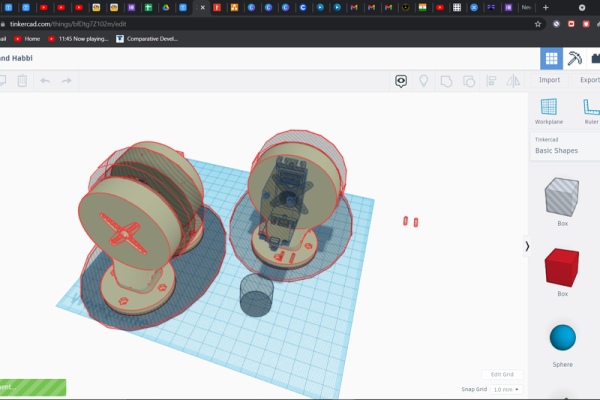
The designing part of it is the most crucial and important step. Keeping in mind that the strength of the end product should withstand its own weight as well as some external weight and torque ( from the object it lifts ).
So after understanding the basic of hand movement that I will go for i.e. finger movement and wrist rotation movement I decided to use as simple shape and design as possible. Also I had a reference point to start with because I had an idea about how should a robotic hand should be designed and made based on numerous videos and open source project that I watched and read.
So I opened up my ThinkerCad account imported a few files and started remixing them according to my need and scope of project. That said many components are completely designed my me for instance the wrist joint (where hand and servo hold joins together) the main arm body and its cap, etc. While most of the work was done in ThinkerCad I sent a few files such that of wrist joint to Fusion360 for some further detailing to the design.
Designed to replicate natural hand position when picking up any object.
MG995 servo motors used have a torque of 2.8 KG/cm at 4.8V in this particular application a constant power of 5V is supplied to all servo motors. When the servo motor rotates, the torque is transferred to string using pulley wheel because of this tension is created in string and this tension forces fingers to actuate to close position. 4 Servos are used to actuate fingers( 1 thumb, 1 index finger, 1 middle finger, 1 for ring and pinky finger). Each Finger have phalanges (biological term for 3 finger bones[see figure]) here I have added a 45° angle at each phalanx so together it can actuate a total of 90° giving a complete natural movement of Human Fingers.
4 Servo each producing 2Kg of force each at 5 fingers. So a total of around 8Kg of closing/squeezing force is experienced at the wrist but the hand can only pick up 1.5~2Kg of weight because of joint strength as force(weight of object picked) applies a resultant torque at elbow and wrist joint.
I have added all the 3D downloadable (.stl) files link below:
Attachments
- elbow joint.stlDownloadView in 3D
- hand arm body.stlDownloadView in 3D
- hand arm cover.stlDownloadView in 3D
- wrist joint.stlDownloadView in 3D
- Servo_Hold.stlDownloadView in 3D
- ServoHorn.stlDownloadView in 3D
- LH_Finger_Plate.stlDownloadView in 3D
- LH_Hand_Body.stlDownloadView in 3D
- Finger_Hinge_Plate.stlDownloadView in 3D
Step 3: 3D Printing
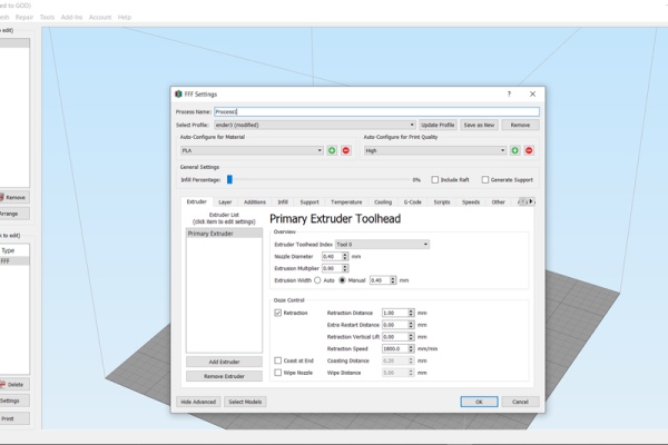
This part is fairly simple after you have downloaded the .stl files open them in your regular or daily slicer software. I use standard Cura and Creality slicer as they are open source and works very well with my upgraded Ender3.
The settings are pretty stock, you can have a look at it from the screenshot that I added. I have used a cheap PLA and TPU for the print and the print came out just fine. My stalk settings are:
Nozzle temp- 200 (PLA), 210(TPU)
Bed temp- 60(PLA), 80(TPU)
Speed- 80mm/s(PLA), 60mm/s(PLA)
Layer height- 0.2mm
Infill- 20%
I have added all Gcode files below:
Attachments
- elbow joint.gcodeDownload
- hand body cover.gcodeDownload
- hand body.gcodeDownload
- LH_Finger_Plate.gcodeDownload
- LH_Hand_Body.gcodeDownload
- Servo_Hold.gcodeDownload
- ServoHorn.gcodeDownload
- Tanmay Robo Potentiometer Stand v1.gcodeDownload
- wrist to body joint.gcodeDownload
Step 4: Assembly and Circuit Diagram
After some clean up of the 3D printed parts now it’s time for the fun part. Follow these steps and guidelines:
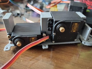
1-The servo horn ( 3d printed pulley ) that you will download needs to be stick with super-glue to the servo horn ( circular black coupling that came with servo MG995 )
2- The servos are to be positioned opposite to each other also the holes for tightening the servo will guide you.
3- Take your nylon thread stretch it and rub candle wax over it and then apply thin layer of super-glue to it. Now cut long 30cm pieces of it. ( this will increase the strength and will prevent thread from unwinding itself )
4- Now take thread and make your hand by passing thread from holes in each 3d printed finger and then guide hole present in 3d printed palm.
5- Now assemble everything. Screw servos in its position using the screw holes in the 3d printed arm body.
6- Now assign one servo each to each finger but make sure to use a single servo for ring and pinky/little finger.
7- After that carefully measure the distance of thread required in open finger position and cut the rest.
8- Knot the thread end to servo Horn ( 3d printed Pulleys ) and put a drop of super-glue over it to make good joint so that it doesn’t loosen up under load.
9- Now screw the servo horn ( Start shaped that comes with servo MG995 ) to the back side of 3d printed arm body.
10- Now use a screw and tighten the servo hold to the servo motor that will handle the rotation of wrist movement.
11-Now carefully using the holes in body of arm take wire out of servo and tie them using thread( just to make everything tidy)
12- Double check your knots and see manually if everything that needs to move is moving in the specified manner.
Step 5: Coding and Trouble Shooting
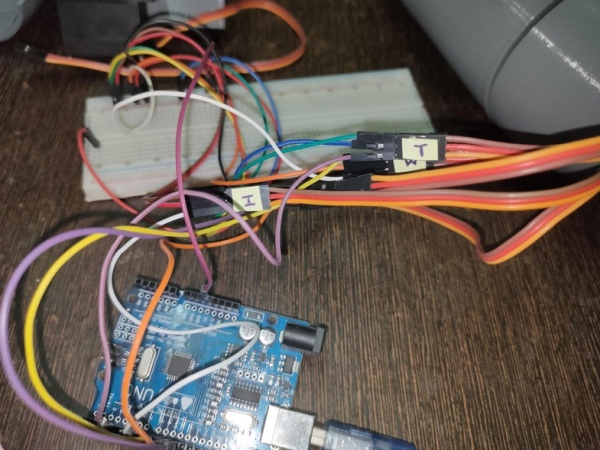
It is again a straight forward step just make sure the wiring is as per the circuit diagram given.
I used an Arduino Uno for this project as its cheap and can handle the work load of this hand very easily.
The video is of test code, the code given below is upgraded and is written to perform Human Hand like movement. Such as each finger closing and opening individually, wrist rotation, object pick-drop, peace sign, etc.
I have uploaded a test code to replicate human finger and hand motion you can try it out. Also change code as per your need and liking.
You can download the .ino file given below.
Attachments
Step 6: Final Overview
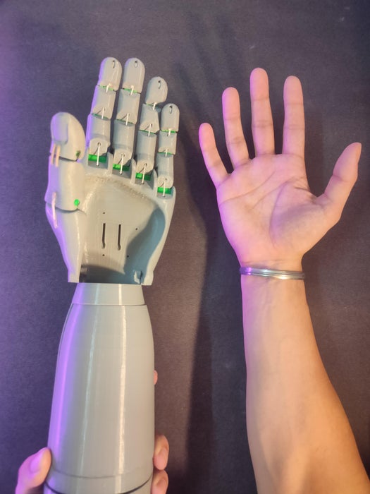
Length*= 42cm
Width**= 10.5cm
Weight***= 580g
Torque= 2.8Kg (each servo)
Gripping strength = ~8Kg
*- from tip of middle finger to elbow join module
**- at the widest point
***- body with motors and circuitry
Source: Cyborg Hand : Robotic-cum-Prosthetic Servo Powered Hand
- What materials are used for 3D printing the hand?
PLA is used for most parts and TPU is used for hinges. - How many servos are required and which model?
Five MG995 servos are used: four for fingers and one for wrist rotation. - Can the hand be controlled by sensors or only by code?
The hand can be controlled by potentiometers, EMG sensors, AR-VR gloves, or direct coding. - How are the fingers actuated?
Finger motion is actuated by nylon string tension routed over 3D-printed pulleys driven by servos, with rubber bands providing push-back. - What electronics are used to control the servos?
An Arduino Uno is used to control the servos and run the provided code. - What printing settings were used for PLA and TPU?
Nozzle temps: 200°C for PLA and 210°C for TPU; bed temps: 60°C for PLA and 80°C for TPU; layer height 0.2 mm; infill 20%. - How strong is the gripping force and how much weight can it lift?
Each servo provides about 2.8 kg·cm torque; combined closing strength is about 8 kg, but the hand can pick up around 1.5–2 kg due to joint strength and torque limits. - Are STL and G-code files provided?
Yes, STL files and G-code attachments for printed parts are provided in the project. - What steps are recommended to prepare the nylon thread?
Stretch the nylon thread, rub candle wax on it, apply a thin layer of super-glue, then cut to length to prevent unwinding. - What are the final dimensions and weight of the assembled hand?
Length 42 cm, width 10.5 cm, and weight approximately 580 g including motors and circuitry.