
Summary of Custom Arduino Shield and Sensors
This article details the construction of custom, uniform-sized sensor modules (1.5cm x 2.5cm) and an Arduino shield for robotics projects. The system utilizes standardized three-pin connectors (Signal-Voltage-Ground) to simplify wiring between sensors and the shield. It covers building leaf switches, buttons, light sensors, IR distance sensors, and ultrasonic distance sensors using perf boards, resistors, and various connectors. The project enables interchangeable configurations on robot decks and includes code for an autonomous obstacle-avoiding robot.
Parts used in Custom Arduino Shield and Sensors:
- Perf boards
- Straight headers
- Right angle headers
- Socket strips
- Three pin cables
- Leaf switches
- Buttons
- Photoresistors
- 10K resistors
- 250K potentiometers
- IR distance sensor
- Ultrasonic distance sensor (HC-SR04)
- Sensor platforms
- Three pin connectors
- Two pin sockets
- Nuts and bolts
- Hot glue
- Shrink tubing
- Four pin cable
- Compatible sensor cable
- Ardunio shield
- White, black, and red wires
Overview:
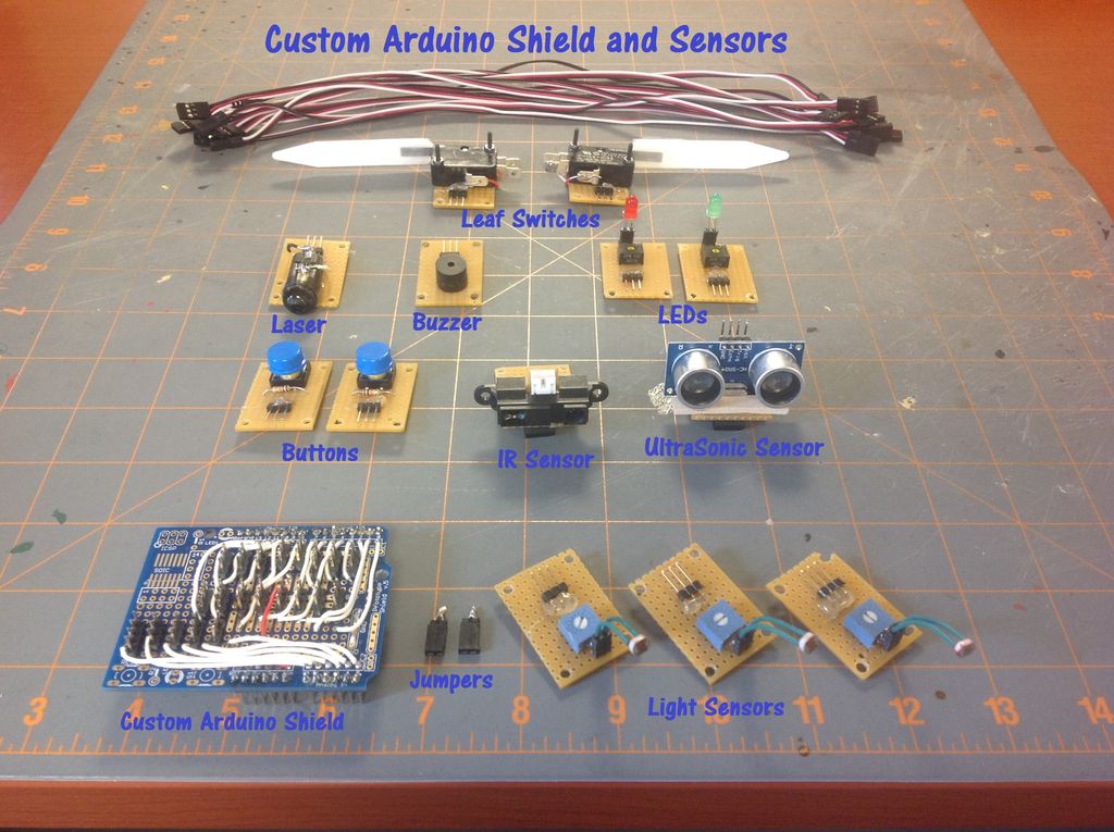
This instructable will construct a series of custom sensor modules and an Arduino shield. Such modules are available from many different sources, but fans of the Instructables website would probably find satisfaction in making their own. Each module will be a set size of 1.5cm by 2.5cm and employ a three pin connector of the form Signal-Voltage-Ground. The custom shield will break out the Arduino pins into the same Signal-Voltage-Ground configuration. Thus, electronic connections will be reduced to using a three pin cable to attach a sensor to its corresponding pin set on the Arduino shield. Uniformly spaced mounting holes at the corners of the modules will allow for interchangeable configurations on a robot deck or in other electronics projects. The embedded video displays the sensors in action on an autonomous obstacle avoiding robot. The Arduino code for the robot is given below. The light sensors described in step three of this instructable were also used in my previous instructable.
The construction of the sensors will involve some basic materials including several perf boards, header strips, socket strips and three pin cables. Both straight and right angle headers will be used. The perf boards need to be cut into several 1.5cm by 2.5cm rectangles with a screw hole drilled into each corner. (See figures in the following steps.) In the following steps, an image note in the upper left will give each figure a number of the form Figure x-x. For example, Figure 2-4 refers to the fourth figure of step two.
Step 1: Leaf Switches
Components:
2x 10K resistors
2x three pin connectors
2x sensor platforms
suitable nuts and bolts
The leaf switches are designed to be used as contact sensors on the sides of a robot. Thus they will be constructed as mirror image pairs, one for the left side and one for the right side of the robot. Placement of the components for the left leaf switch are shown on the left in Figure 1-2. I hot glued the three pin connector into place, but I used nuts and bolts to secure the switch itself to the sensor platform for greater stability. Solder a white wire from normally open contact on the switch to the signal pin of the sensor. See figure 1-3. (Note, for all of the sensors in this instructable, when the three pin connector is positioned on the sensor platform and pointing down, the pin order from left to right is Signal, Voltage, Ground. Of course when viewing the back side of the sensor, the order from left to right is Ground, Voltage, Signal.) Next, solder a white wire from the signal pin to one lead of the 10K resistor. Solder a black wire from other end of the 10K resistor to the ground pin. Finally, solder a red wire from the common contact of the switch to the voltage pin. The resistor pulls the signal pin low. Pressing the switch then pulls the signal pin high.
Step 2: Buttons
Components:
2x buttons
2x 10K resistors
2x three pin connectors
2x sensor platforms
Hot glue the components into place as shown on the left of Figure 2-2. On the back side of the sensor, bend the resistor leads toward the outer pins of the three pin connector and solder. Solder a white wire from the signal pin to one side of the switch. Solder a red wire from the voltage pin to the other side of the switch. Don’t forget to solder all four switch leads for stability. (I originally only soldered the two leads connected to the wires and the button began to rock back and forth.)
Step 3: Light Sensors
Components:
3x 250K potentiometers
3x two pin sockets
3x three pin connectors
3x sensor platforms
The directions given here will closely mirror those of my previous instructable. Each light sensor will consist of a voltage divider made from a photoresistor and a 250K potentiometer. First, hot glue the components into place as shown in Figure 3-2. Bend the leads of the potentiometer as show in Figure 3-4. Take a white wire and solder the right most connector pin (as viewed from the back) to the potentiometer wiper and right socket lead. Use a red wire to solder the left socket lead to the right potentiometer lead and the center connector pin. Use a black wire to solder the remaining potentiometer lead to the remaining connector pin. Next, place some shrink tubing around the legs of the photoresistors before inserting them into the sockets. See Figure 3-5. This gives the sensor a nice finished look and of course also prevents shorts. (I picked up this shrink tube tip from BIGDOG1971‘s light following robot instructable.) These voltage dividers can also be used with other sensors such as flex sensors and force sensors.
Step 4: IR Distance Sensor
Components:
1x sensor platorm
For this module I simply hot glued the IR sensor to the sensor platform.
Step 5: Ultrasonic Distance Sensor
Components:
1x four pin cable
1x sensor platform
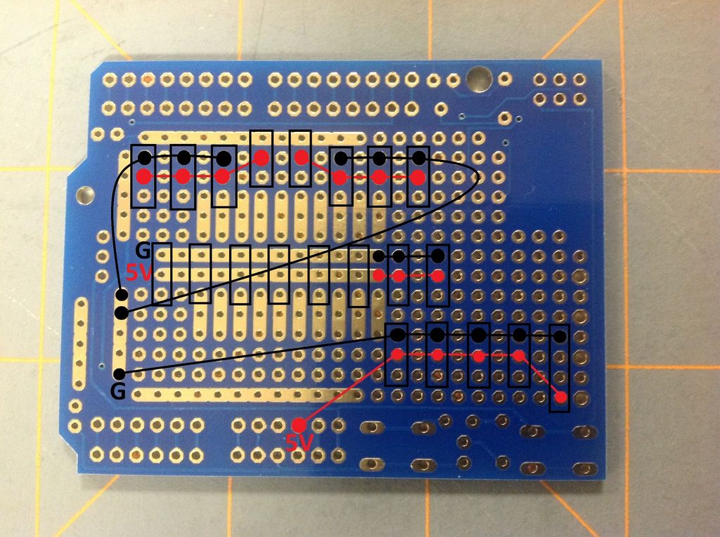
Again, this module consists of the the sensor hot glued to the sensor platform. You may want to use a small piece of wood or cardboard under the “eyes” of the sensor since it does not quite fit on the platform. Also, the HC-SR04 sensor that I used does not conform to the three pin configuration of the other sensors. This requires a dedicated four pin node on the Arduino shield as described in Step 10.
For more detail: Custom Arduino Shield and Sensors
-
What are the dimensions of the custom sensor modules?
Each module is a set size of 1.5cm by 2.5cm. -
How many pins does the standard connector use for these sensors?
The modules employ a three pin connector with the configuration Signal-Voltage-Ground. -
Why were nuts and bolts used for the leaf switch instead of just hot glue?
Nuts and bolts were used to secure the switch itself to the sensor platform for greater stability. -
Does the HC-SR04 ultrasonic sensor use the standard three pin configuration?
No, the HC-SR04 sensor does not conform to the three pin configuration and requires a dedicated four pin node. -
What is the purpose of placing shrink tubing around the legs of the photoresistors?
It gives the sensor a finished look and prevents shorts. -
How should the resistor be wired in the button sensor circuit?
Bend the resistor leads toward the outer pins of the three pin connector on the back side and solder them. -
What happens to the signal pin when a leaf switch is pressed?
Pressing the switch pulls the signal pin high after the resistor normally pulls it low. -
Can the voltage dividers described for light sensors be used with other components?
Yes, these voltage dividers can also be used with other sensors such as flex sensors and force sensors.
