Summary of Crocodile Solar Pool Sensor
This project, the "Crocodile Solar Pool Sensor," is a solar-powered, WiFi-enabled pool temperature sensor using an ESP8266 (Wemos D1 mini pro) that sends temperature and battery voltage data to the Blynk app and an MQTT broker. It features a waterproof DS18B20 temperature sensor, solar charging via a LiPo battery, and a creative crocodile head housing for outdoor use. The sensor supports Celsius/Fahrenheit display, low power consumption, reprogrammability, and includes careful waterproofing measures like epoxy seals and a 3D-printed USB port cover for updates.
Parts used in the Crocodile Solar Pool Sensor:
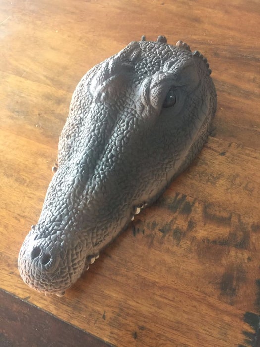
- Crocodile head (foamed plastic)
- ESP8266 Wemos D1 mini pro board
- Solar panel 0.25W 45x45mm
- 3.7V 1000mAh LiPo rechargeable battery
- Battery charger module TP4056
- Waterproof temperature sensor DS18B20
- 22 AWG wire
- Prototype PCB board 5x7cm
- 220 Ohm resistor
- 4.7 kOhm resistor
- Short USB to MicroUSB cable
- Epoxy glue (2-component)
- Hot glue
- Insulating foam sealant
- Waterproof paint
- Filler primer spray
- Liquid epoxy for waterproof coating
- 3D printed protective cover for USB port (optional)
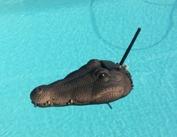
This instructable shows how to build a rather special pool sensor measuring the pool temperature and transmitting it via WiFi to Blynk App and to a MQTT broker. I call it the “Crocodile Solar Pool Sensor”.
It uses the Arduino programming environment and an ESP8266 board (Wemos D1 mini pro).
What’s so special about this project?
- The look is just great
- Fully independent from power sources (solar panel feeds the LiPo battery)
- Low power ESP8266 WiFi connected sensor
- Rather high precision temperature sensor
- Data transmission of temp and voltage to Blynk APP for your mobile phone
- Sends also a “last updated” timestamp to Blynk APP
- Data transmission of temp and voltage to a MQTT broker
- Celsius and Fahrenheit switchable
- Can be reprogrammed
Your skill level: intermediate to experienced
Supplies:
For this build you will need to know how work with:
- Arduino IDE (programming environment)
- a soldering iron
- a drill
- a sharp knife
- epoxy glue
- hot glue
- industrial spray foam
- spray color
Step 1: Components Needed
These things are needed to build this nice pool sensor:
- The crocodile head (foamed plastic) found here: Amazon: Crocodile Head
- ESP8266 Wemos D1 mini pro: (Aliexpress)
- Solar Panel 0.25W 45x45mm: (Aliexpress)
- 3.7V 1000mAh LiPo rechargeable battery: (Aliexpress)
- Battery charger module TP4056: (Aliexpress)
- Waterproof temperature sensor DS 18b20: (Aliexpress)
- 22 AWG wire (Aliexpress)
- Prototype PCB board 5x7cm (Aliexpress)
- 220 Ohm and 4.7 kOhm resistors
- a short USB to MicroUSB cable
additionally:
- Insolating foam sealant @ DIY market or here: (Amazon)
- Waterproof paint @ DIY market or here: (Amazon)
- Filler primer spray @ DIY market or here: (Amazon)
- Liquid epoxy for a waterproof coating @ DIY market
- Hot glue
You might need to use a 3D printer to print a waterproof cover for the USB port.
Step 2: Electronics
I thought it is easiest to start with some of these DIY universal prototype PCBs and I found that a 5x7cm is just perfect for this purpose.
Building steps:
- Prepare the D1 mini pro for using an external antenna:
- Unsolder 0 Ohm resistor next to ceramic antenna
- Turn 0 Ohm resistor downwards and solder the connection to external antenna (good explanation found here – Step5)
- Place the parts and decide for the layout on the prototype PCB before you start soldering
- Solder the the pins to the D1 mini pro
- Solder the standoff pins to the prototype board
- Solder the pins for the charger board to the prototype PCB
- Solder the charger board to the pins
- Cut the cable of the temperature sensor to a length of 20 cm
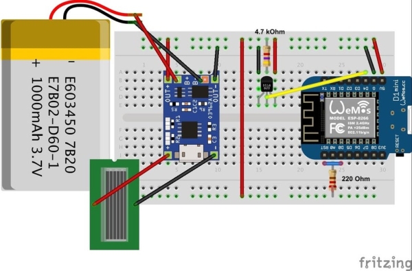
- Please see image above for connecting the temperature sensor
- Solder the cable to the solar panel
- DO NOT YET solder the solar panel cables to the board – these need to be glued first to the crocodile’s head
- Follow the Fritzing schema above to solder all the remaining connections to the PCB
- Once all components are connected and soldered use some hot glue to fix the battery
Please note: For putting the ESP8266 to sleep it is necessary to connect pin D1 with pin RST. Sometimes the D1 mini pro causes problems with the serial port if port D0 and RST are connected. The one I used (see Aliexpress link above) did not have this problem.
If you are facing this problem you might need to use a jumper or a switch to deconnect the two pins for uploading new code. But (!) then you have no chance to reprogram once the crocodile head has been sealed. In this case you also do not need to bring the USB port to the outside (e.g. to drill a third hole).
Step 3: Hardware Part 1 (Preparation of the Crocodile Head)
In this step we prepare the backside of the crocodile head to get enough space for the electronics. And we are drilling some holes for the antenna, the solar panel and the USB port.
I planned my project first without the USB port. But then I thought that it would be impossible for me to do some software updates once the crocodile has been sealed again. Therefore I decided to use a short USB cable micro-USB to USB to allow an outside access to the ESP8266 board.
Next steps to do:
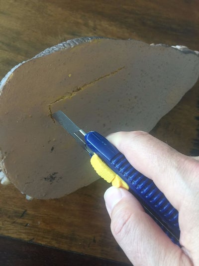
- Use a sharp knife to cut a little more than 7×5 cm (size of your prototype board) off the hard surface
- Use a spoon to remove the softer foam from the inside
- Just make sure that you have enough space for your cables and your board
- Try out if it fits and that there is still some space to cover it later
Now drill two or three holes into the head:
- for the solar panel
- for the antenna
- (optional) for the USB port for enabling later programming
Use 2 component epoxy (5 minutes) to glue and seal these holes again. Use enough epoxy glue! Make sure that it will be waterproof afterwards!
- Glue the solar panel cable to the head and properly seal the hole
- Glue the solar panel between the eyes
- Glue the antenna socket to the head and properly seal the hole
- Glue the USB plug and properly seal the hole
To avoid any water causing corrosion to the USB port I 3D-printed a little protective cap.
Read more: Crocodile Solar Pool Sensor