Summary of Crius ROT8 MIDI Controller [ABLETON READY – Auto Mapping] Rev1.1
This project builds the Crius ROT8 MIDI controller: an 8-potentiometer, 3-button device with 8 LEDs and an LCD showing potentiometer percentages. It uses an Arduino Pro Micro, a PCA9685 LED driver, a 4051 multiplexer, and a custom PCB plus a 3D-printed two-part case. Optional Ableton Live auto-mapping script maps controls to tracks and transport. The guide covers PCB design, assembly, wiring, Arduino code and libraries, 3D printing, and installing the Ableton remote script, with links and software recommendations.
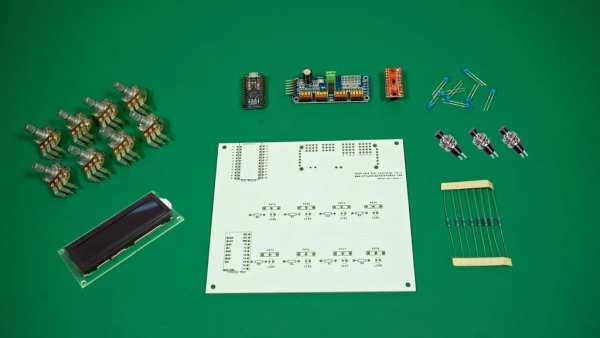
Parts used in the Crius ROT8 MIDI CONTROLLER:
- Crius Rot8 PCB x1
- Arduino Leonardo Pro Micro (clone) x1
- Linear Rotary Potentiometers 10 KOhm Right Angle x8
- Momentary Switches 7mm x3
- 1602A LCD Display x1
- Multiplexer 4051 x1
- PWM Led Controller / Servo Driver PCA9685 x1
- LEDs 3mm x8
- Resistors 220Ohm x8
- Micro USB cable x1
- Trimer Potentiometer 10K x1
- Mini Breadboard x1
- Jumper wires
The last couple of years I started learning about electronics from nothing to be able to build my own MIDI controllers that would serve my needs , taste and be cheaper overall in comparison with the branded products.
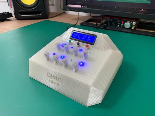
This is CRIUS ROT8 MIDI CONTROLLER that consists of 8 potentiometers and 3 buttons with which we can control the parameters of the VST-Plugin or the DAW that we play music ,
8 LEDs whose brightness varies depending on the position of the corresponding potentiometer as well as an LCD screen that shows the percentage of 100 for each potentiometer so that we can know at a glance the value of the parameter we have assigned it.
The Crius ROT8 comes with a Script which allows us to automatically match (Auto Mapping) each of the 8 penometers with the corresponding Volume of 8 Tracks and the 3 buttons with PLAY, STOP and REC respectively, selecting Crius Rot8 as Control Surface from Menu Options -> Preferences -> Midi -> Control Surface (details for installing Script can be found below).
If we do not use the Script we can do Mapping with anything we want in the DAW.
Step 1: Supplies
HARDWARE COMPONENTS :
1. Crius Rot8 PCB x1
2. Arduino Leonardo Pro Micro (clone) x1
3.Linear Rotary Potentiometers 10 KOhm Right Angle x8
4.Momentary Switches 7mm x3
5.1602A LCD Display x1
6.Multiplexer 4051 x1
7. PWM Led Controller / Servo Driver PCA9685 x1
8.LEDs 3mm x8
9.Resistors 220Ohm x8
10.Micro USB cable x1
11.Trimer Potentiometer 10K x1
13.Mini Breadboard x1
14.Jumper wires
SOFTWARES USED :
FUSION 360 (CAD)
Fritzing (Schematic Designing)
Arduino IDE
Ultimaker CURA (3D-Printing Software)
ABLETON Live (DAW) – OPTIONAL to use the auto mapping script
Step 2: Step 1: Designing the PCB
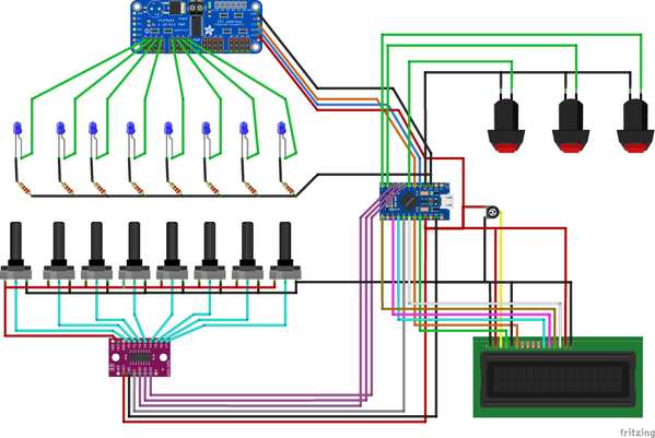
I used Fritzing to design the circuit for the potentiometers , leds , buttons and added some pins to connect a little shield for the LCD display separately so it can be mouted in an angle to the 3D printed case.
Step 3: Assembling the PCB
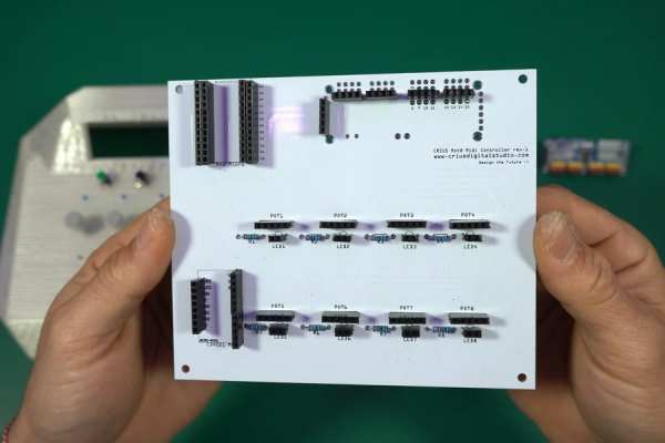
Start by soldering the resistors to the positions that write R and next to the number of each resistor.
(Optionally you could solder first female headers to be able to replace components in the future)
Next we will install the PCA9685 PWM Module , the Arduino Pro Micro and the 4051 Multiplexer.
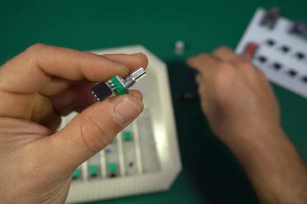
Step 4: Prepairing the Potentiometers , LEDs and Buttons to Be Mounted to the 3D Printed Case
Now OPTIONALLY
1.Solder 3 female headers on each potentiometer
2. 2 female headers on each LED
3. 2 female headers on each button
You can solder the jumper wires directly to the components if you want but I find it more helpful to add the female headers for easier assembly of the 3D printed case and maintenance of the device in the future.
Step 5: LCD Display Shield
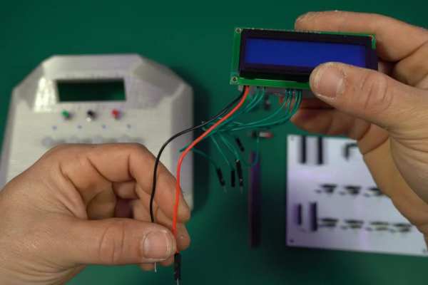
So according to this circuit we need to make a Shield to connect the display to the Arduino which will look something like this
Step 6: Upload the Code
I used Arduino IDE to write and upload the code to the Arduino pro micro.
I used the following Libraries for the code :
1.LiquidCrystal
2.Control Surface
3.Adafruit PWMServoDriver
4.Wire
5.Keyboard
(A BIG THANKS to “Pieter P” the creator of the Control Surface library for his GREAT work!)
You must manually download and install the Control Surface library to the Arduino IDE
Step 7: Design and 3D Print the Case
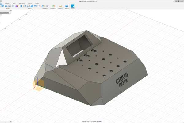
I used FUSION 360 to design the Case dor the MIDI Controller and Ultimaker Cura to slice it.
The case consists of 2 parts :
Body and Bottom base.
For the printing settings I suggest to print it with supports.
Step 8: Ableton Live Auto Mapping Script
Optionally we can add a custom SCRIPT for Auto Mapping of potentiometers and buttons to ABLETON by copying this folder named CriusRot8 to the following folder on your computer:
C: \ Users \ ”TO YOUR USER NAME” \ AppData \ Roaming \ Ableton \ Live 11.1.1 \ Preferences \ User Remote Scripts
(Note that the file directory may be different for you depending on the version of the Ableton you have)
ATTENTION :
The AppData folder is hidden, so you have to click :
View -> Show Hidden Files in the folder menu at the top of the window
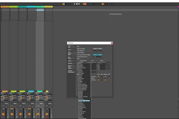
Now that you copied the script folder to the software directory on your drive , connect the MIDI controller to your PC , open Ableton Live and to select :
CriusRot8 as Control Surface from Menu Options -> Preferences -> Midi -> Control Surface
Step 9: Download Links for Softwares
1.Arduino IDE : https://www.arduino.cc/en/software
2.FUSION 360 : https://www.autodesk.com/products/fusion-360/personal
3.Fritzing : https://fritzing.org/download/
4Ultimaker Cura : https://ultimaker.com/software/ultimaker-cura
Step 10: END
I hope you enjoyed the proccess and made one for your self!
You can find everything you need for this project INCLUDING INSTRUCTIONS IN ENGLISH to my website : www.criusdigitalstudio.com
You can find my projects and support me at the following social media and websites:
1.Crius Digital Studio Youtube Channel
2.Crius Digital Studio Thingiverse Profile
3.Crius Digital Studio Github Profile
Source: Crius ROT8 MIDI Controller [ABLETON READY – Auto Mapping] Rev1.1
- What does the Crius ROT8 MIDI controller consist of?
It consists of 8 potentiometers, 3 buttons, 8 LEDs, and a 1602A LCD display on a Crius Rot8 PCB with an Arduino Pro Micro, PCA9685, and 4051 multiplexer. - Can the Crius ROT8 auto-map to Ableton Live?
Yes, using the provided CriusRot8 user remote script placed in the Ableton User Remote Scripts folder you can auto-map the 8 potentiometers and 3 buttons. - How do I connect the LCD display to the controller?
Make a small shield following the provided circuit to connect the 1602A LCD to the Arduino Pro Micro so it can be mounted angled in the 3D printed case. - Which Arduino libraries are required for the code?
The project uses LiquidCrystal, Control Surface, Adafruit PWMServoDriver, Wire, and Keyboard libraries. - What software is used to design and print the case?
Fusion 360 was used for CAD and Ultimaker Cura for slicing the 3D-printed two-part case (body and bottom base). - Do I need to solder female headers to components?
Optionally you can solder female headers to potentiometers, LEDs, and buttons for easier assembly and future maintenance, but you can also solder jumper wires directly. - Where do I place the CriusRot8 script for Ableton?
Copy the CriusRot8 folder to C:UsersTO YOUR USER NAMEAppDataRoamingAbletonLive 11.1.1PreferencesUser Remote Scripts (path may differ by Ableton version). - What is the role of the PCA9685 in the project?
The PCA9685 is used as the PWM LED controller to drive the brightness of the 8 LEDs according to potentiometer positions.