Summary of Creating Mini Digital Roulette Games with Arduino.
Crafting straightforward electronic games with Arduino, this chapter shows how to build two Mini Digital Roulette games (LED bar and seven-segment versions) using basic parts and simple circuits. It covers system design, wiring, LED forward-bias calculations, testing methods, Arduino sketches for both roulette and a seven-segment flasher-tester, and upgrades such as a potentiometer-controlled speed and using a 7490 counter plus 7447 decoder for numeric output.
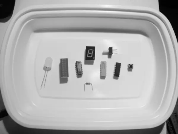
Parts used in the Mini Digital Roulette:
- Arduino Duemilanove or equivalent
- LED bar display (bar graph LED display)
- 2x8 330W DIP resistor IC (330 Ω resistors)
- Big LED (large blue LED shown)
- Push-button switch (tactile or equivalent)
- 10K trimmer potentiometer
- 10K resistor (pulldown)
- 7490 / 74LS90 Decade Counter IC
- 7447 / 74LS47 Seven-Segment Decoder Driver IC
- Common Anode Seven-Segment LED Display (MAN 72)
- Small solderless breadboard (and optional extra mini breadboard)
- 22 AWG solid wire (jumper wires)
- Digital multimeter (DMM)
- Oscilloscope (optional)
- Electronic tools
Crafting straightforward electronic games becomes effortless with the Arduino. Within the scope of this chapter, I will demonstrate the possibility of constructing an interactive mini casino game using fundamental digital electronic circuits within a mere two-hour timeframe. By leveraging just nine distinct electronic elements and an Arduino board, you’ll find it a breeze to assemble a pair of captivating Mini Digital Roulette games.
Parts List
1 Arduino Duemilanove or equivalent
1 LED bar display (also called a bar graph LED display)
1 2×8 330W DIP resistor IC
1 big LED
1 push-button switch (tactile or equivalent)
1 10K trimmer potentiometer
1 10K resistor
1 7490/74LS90 Decade Counter IC
1 7447/74LS47 Seven-Segment Decoder Driver IC
1 Common Anode Seven-Segment LED Display (MAN 72)
1 small solderless breadboard
22 AWG solid wire
Digital multimeter
Oscilloscope (Optional)
Electronic tools
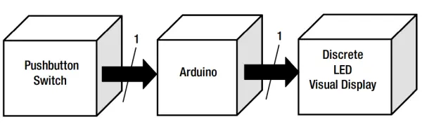
Within this chapter, I’ll demonstrate how the two devices exemplify a design approach in which a novel product emerges from a more straightforward blueprint. This innovative “remix” design method empowers product designers and developers to expedite their market entry without extensively overhauling the bill of materials (BOM). Refer to Figures 2-2 and 2-3 for the system block diagrams of the two Mini Digital Roulette games.
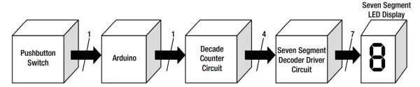
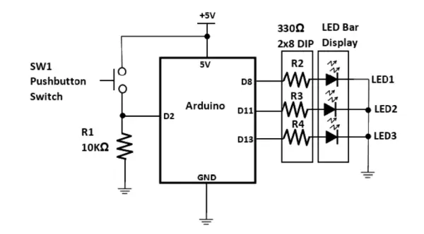
Examining the system block diagram more closely unveils the circuit schematic of the LED roulette game, as depicted in Figure 2-4. The numerals positioned above the arrows indicate the count of pins employed between the two modules. This data will prove significant in the context of the mini roulette game’s seven-segment LED display variant.
How It Works
The LED roulette game operates by having the Arduino detect a rising edge from a simple push-button switch. When the +5VDC control signal is received, the Atmega328 microcontroller, programmed with specific software, initiates the sequential switching of the three LEDs within the LED bar display. The software rapidly activates the LEDs according to a predetermined switching pattern, gradually decelerating until only one LED remains illuminated. With each press of the push-button, the switching cycle repeats, lighting up a different LED each time. To ensure the Arduino’s Atmega328 microcontroller detects the +5VDC, a 10K pulldown resistor is incorporated in series with the push-button switch. The circuit schematic diagram in Figure 2-4 outlines the specific wiring orientation for each LED within the bar display. The adopted wiring convention guarantees proper illumination of the LEDs based on the corresponding switched output port (D8, D11, D13) through a process known as forward biasing.
Note: Take note that a rising edge in a digital control signal denotes a shift from 0V to either +3.3V or +5V. The term “pulldown” signifies the application of the supply voltage across the connected resistor, guaranteeing that the microcontroller’s input port pin recognizes it as a valid binary logic “1” data value. This recognition is crucial for accurate processing of the control signal.
Forward Biasing a LED
Take note that a rising edge in a digital control signal denotes a shift from 0V to either +3.3V or +5V. The term “pulldown” signifies the application of the supply voltage across the connected resistor, guaranteeing that the microcontroller’s input port pin recognizes it as a valid binary logic “1” data value. This recognition is crucial for accurate processing of the control signal.
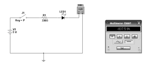
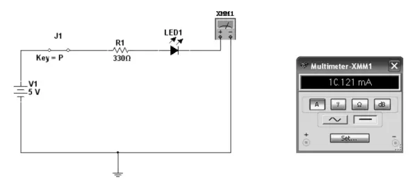
LED Circuit Analysis
The current resulting from forward biasing, as depicted on the virtual ammeter in Figure 2-6, can be manually computed (using pen and paper) utilizing the subsequent equation:
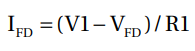
where
• IFD is the forward current of the LED.
• V1 is the supply voltage.
• VFD is forward voltage drop of the LED (Note: 1.66 V is the value for this component
parameter).
• R1 is the series limiting resistor.
So, making the appropriate substitutions into the equation
IFD= (5V -1.66V )/330Ω
IFD=3.34V / 330 Ω
IFD= 0.01012A or 10.12mA
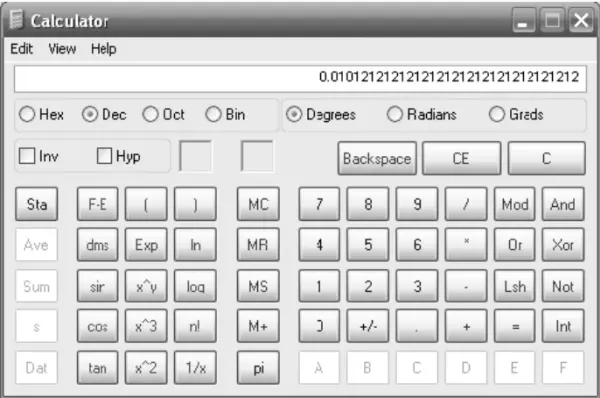
The practical solution carried out using the Windows Calculator is illustrated in Figure 2-8.
The LED Bar Display
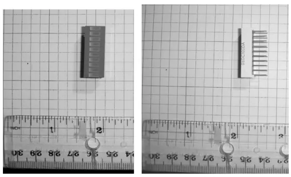
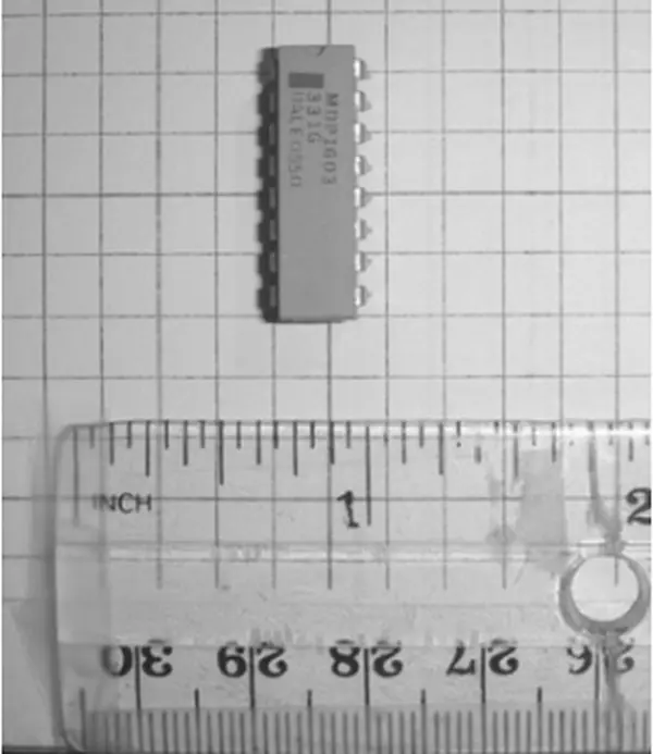
Illustrated in Figure 2-4, the visual representation of the Mini LED Roulette game adopts a bar display design. LED bar displays encompass an assortment of separate solid-state indicators, varying from 4 to 10 components within a single Dual In-Line Package (DIP). In the context of this Arduino-based electronic game, the employed DIP IC package contains 10 distinct LEDs, as exemplified in Figure 2-9. The anode pins of the DIP IC package are situated on the side bearing the part number.
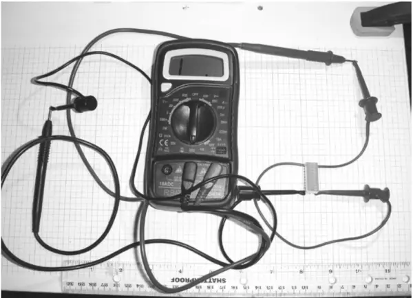
Verifying an LED bar display can be effortlessly accomplished by utilizing a Digital Multimeter (DMM) configured to measure resistance. Contemporary DMMs come equipped with a diode test feature, which proves useful for LED testing. To initiate the test, select the diode testing mode on the DMM, then attach the red test lead of the measuring device to the anode pin, while connecting the black test lead to the cathode. The configuration for connecting the DMM to the LED bar display is depicted in Figure 2-10. While the DMM’s LCD may indicate an open circuit, the individual LED linked to it will actually illuminate. This illumination occurs due to the slight current supplied by the ohmmeter, which forward biases the LED and thus causes it to emit light.
The testing methodology covered in this discussion can be employed for assessing a seven-segment LED display. In addition to demonstrating the testing process for the seven-segment LED display, I will provide an explanation of the operational principles behind this optoelectronic component.
Note Optoelectronics encompasses a technology that amalgamates light and electronic circuits, incorporating elements like LEDs, seven-segment LED displays, and LCDs as prime instances.
Mini Roulette Game, Version 1
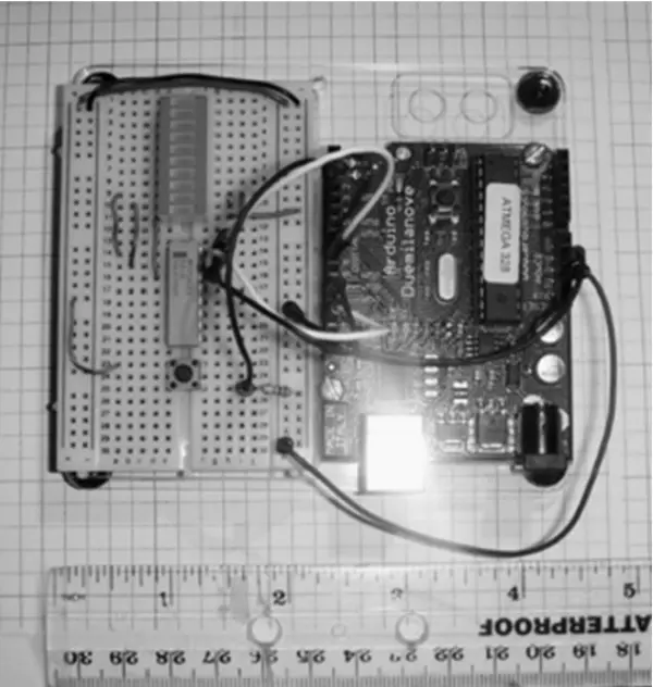
Depicted within the circuit schematic diagram of Figure 2-4, the initial iteration of the Mini Digital Roulette game demonstrates a relatively straightforward electronic design. This design holds an experimental nature; it offers an avenue for self-discovery through the addition of LEDs and the modification of sketches to accommodate supplementary solid-state indicators. Employing a solderless breadboard in conjunction with the Arduino, the prototype game’s construction is facilitated. Figure 2-12 provides a visual representation of the finalized prototype game.
Upon a momentary press of the push-button switch, the trio of LEDs commences a swift lighting sequence, each swiftly activating. This sequence iterates several times before gradually slowing the switching rate. Upon reaching this output stage, one of the LEDs remains illuminated, denoting the conclusion of the game with the designated winning number. The specific LED that remains lit is determined by a randomly selected switching pattern governed by the embedded sketch.
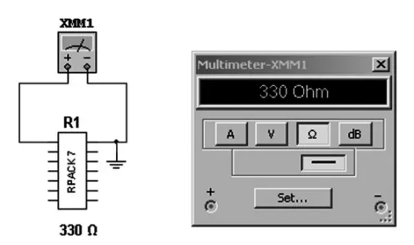
When assembling the Mini Digital Roulette game, the LED bar display and the 330 Ω DIP resistor are both affixed onto the compact solderless breadboard, maintaining suitable spacing to accommodate jumper wires. A DIP package typically contains eight 330 Ω resistors, as depicted in Figure 2-13. These resistors serve the purpose of regulating the current flow through each individual LED within the bar display IC. Positioned between parallel pins, each resistor ensures proper current distribution.
For confirmation of component arrangement, employ an ohmmeter to test. Connect the red and black test leads of the ohmmeter to the parallel pins, as illustrated in Figure 2-14. The ohmmeter’s LCD screen will display the resistance measurement of a single 330 Ω resistor, and this identical measurement technique can be employed to validate the remaining 330 Ω resistors.
Adding the Game Software
The conclusive stage in completing the first version of the Mini Digital Roulette game involves incorporating the sketch. The sketch for the mini roulette game is presented in Listing 2-1.
Listing 2-1. The Mini Digital Roulette Game Sketch
/*Arduino LED Roulette
Posted by changb3 in Class Notes
Connect 3 LED’s to digital output pins 8, 11, and 13 (with resistors in serial with each).Connect a push-button to pin 2 (and don’t forget the pulldown resistor).
[code]
Modified by Don Wilcher 11/17/11
/*
random light
*/
const int buttonPin = 2;
int lightpins[3] = {8,11,13};//Change sequence of LEDs Here!
int state=0;
void setup()
{
pinMode (buttonPin,INPUT);
pinMode (lightpins[0],OUTPUT);
pinMode (lightpins[1],OUTPUT);
pinMode (lightpins[2],OUTPUT);
digitalWrite (lightpins[0],LOW);
digitalWrite (lightpins[1],LOW);
digitalWrite (lightpins[2],LOW);
}
void loop ()
{
int reading = digitalRead (buttonPin);
int blinktime=20;
boolean done;
if (reading == HIGH)
{
if (state==0)
{
state=1;
done=false;
blinktime=20;
blinktime+= 3;
while (!done)
{
for (int j=0;j<3;j++)
{
blinktime += random(3);
digitalWrite(lightpins[j],HIGH);
if (blinktime>200)
{
done=true;
break;
}
delay(blinktime);
digitalWrite(lightpins[j],LOW);
delay(blinktime);
}
}
}
}
{
else
{state=0;
}
}
What makes the Arduino computing platform truly remarkable is the extensive community of developers generating open-source software tailored for a wide array of hardware gadgets and devices. I discovered that the remix approach to software development was notably straightforward to execute, primarily owing to the abundance of sketches accessible online through forums and virtual communities of hobbyists. The provided sketch serves as an illustrative instance of remixing due to its incorporation of random bit selection once the game concludes. The code lines responsible for generating the randomized LED displays are outlined as follows:
blinktime += random(3);
digitalWrite(lightpins[j],HIGH);
if (blinktime>200)
Following the cessation of the game, the initial sketch maintains the presentation of the last bit on the LED bar display. A fresh sequence for the LED display can be implemented through the utilization of the subsequent code line:
“`cpp
int lightpins[3] = {8,11,13};//Modify LED sequence Here!
“`
Modifying the arrangement of digital output pins (8, 11, 13) will result in distinct visual effects for the Mini Digital Roulette game.
The Seven-Segment LED Display Basics
While the LED bar display offers a distinctive method of depicting a spinning roulette ball, comprehending the chosen number can prove challenging due to its binary format. The forthcoming enhancement for the Mini Digital Roulette game entails substituting the LED bar display with a numeric digit. This design modification enhances the electronic product by ensuring clear visibility of the numbers throughout the game. The seven-segment LED bar display shares similarities with the LED bar display, but with the added feature that each segment is positioned to exhibit a number or character. Figure 2-15 provides a depiction of the internal configurations of every LED segment within the optoelectronic display.
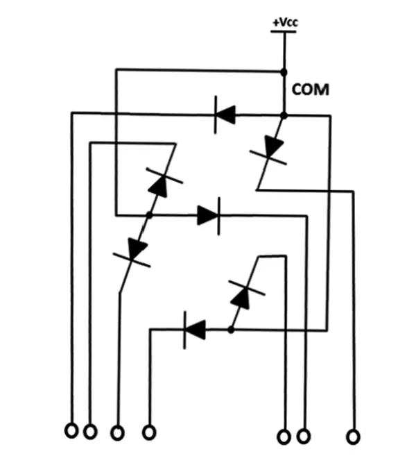
Observe that all anodes are linked to a shared electrical node, forming a central connection. This configuration designates the display package as a common anode seven-segment LED display. Conversely, a common cathode display exists, where all individual LED cathodes are interconnected to a solitary electrical point or pin on the DIP component. Another prominent physical attribute is the count of distinct LEDs—seven in total within a single package—hence the name seven-segment LED display. A representative example of a seven-segment LED display component is illustrated in Figure 2-16.
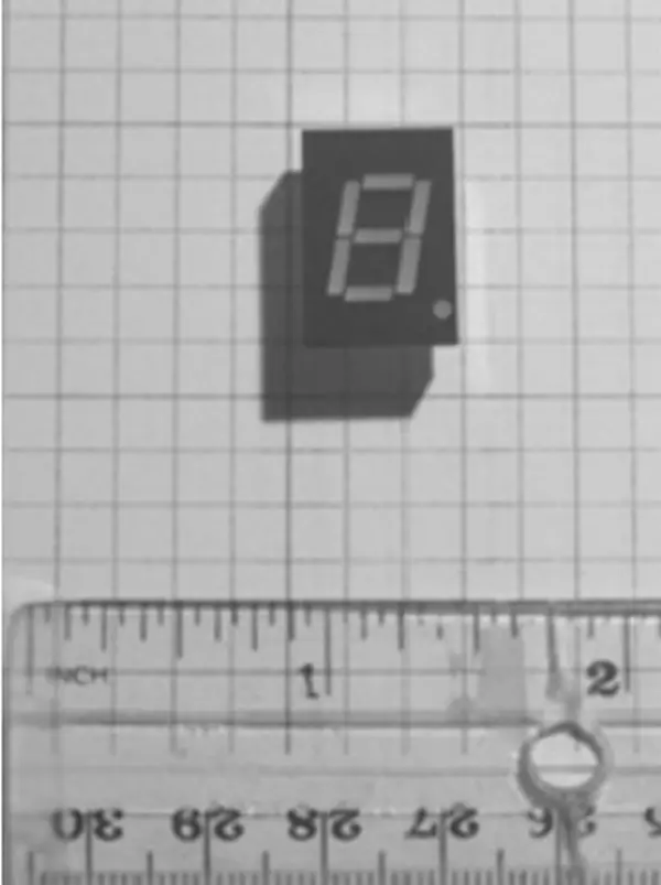
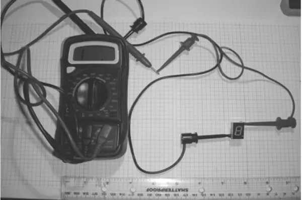
Testing the Seven-Segment LED Display
You’ll observe that testing a seven-segment LED display follows a pattern akin to assessing a basic silicon diode. When you connect the red test lead of the ohmmeter to the common anode pin and attach the black test lead to one of the cathode pins on the seven-segment LED display, the optoelectronic component will be forward biased by the meter. Figure 2-17 outlines the configuration for testing a seven-segment LED display, employing a Digital Multimeter (DMM) set in ohmmeter mode.
As a result of forward biasing, the individual LED segment will illuminate. In the testing scenario depicted in Figure 2-18, the lower-left segment is activated. Another noteworthy aspect of seven-segment LED displays is the assignment of letters to each distinct LED element. These segments are designated with seven letters, ranging from A to F. By interconnecting these letters in various combinations, you can form alphanumeric characters and numerals. In the enhanced iteration of the Mini Digital Roulette game, numbers 0-9 will be showcased on the seven-segment LED display. This method of representing the spinning ball within the roulette wheel elevates the game’s visual appeal, surpassing the repetitive scanning of three LED bars.
Note Prior to the advent of solid-state seven-segment LED displays, digital data was conveyed through Nixie Tubes, reminiscent of compact vacuum tubes containing neon light segments arranged within their glass enclosures.
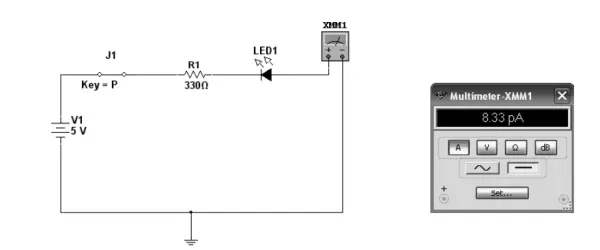
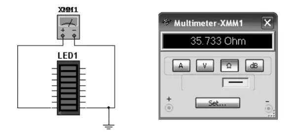
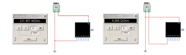
Multisim (or a comparable circuit simulation software) serves as a valuable tool for demonstrating the procedure to test a seven-segment LED display. Rather than activating the specific LED segment in question, the ohmmeter will indicate an exceedingly high resistance value (measured in giga-ohms) for a faulty LED (open circuit). Conversely, a functional LED segment will exhibit a resistance in the range of several hundred mega-ohms on the ohmmeter. Although the seven-segment LED display models within Multisim exhibit accuracy, Figure 2-19 provides a visual representation of a properly functioning LED segment (in forward biasing mode) juxtaposed with a malfunctioning optoelement depicted in reverse biasing mode.

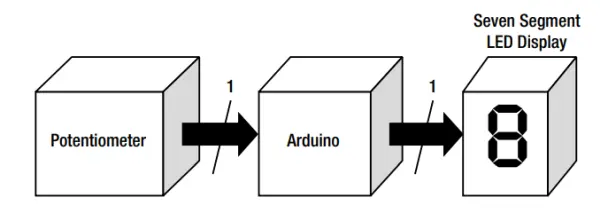
Build an Arduino-based Seven Segment LED Display Flasher-Tester
Creating a digital clock using the Arduino alongside a straightforward seven-segment LED tester is a seamless endeavor. The pulse or flashing frequency of the digital clock can be finely tuned through the utilization of a potentiometer. Configuring the seven-segment LED display to represent a particular alphanumeric character or numeral permits the examination (flashing) of intended segments on the optoelectronic unit. The block diagram of the Arduino Flasher-Tester is depicted in Figure 2-20.
The system block diagram’s circuit schematic is depicted in Figure 2-21. Altering the resistance of the potentiometer introduces varying input voltages, influencing the flash rate of the seven-segment LED display. Within the Arduino’s microcontroller, a range of corresponding analog-to-digital count values extends from 0 to 1024 bits. These values are employed by the embedded sketch within the Arduino’s Atmega328 microcontroller to generate a distinct flash rate for the digital clock signal at pin D13. The chosen LED segments designated for visual presentation will pulsate according to the predefined rate set by the sketch. Rotating the 10 K potentiometer either clockwise or counterclockwise instigates the seven-segment LED display to alternate between slower and faster flashing speeds.
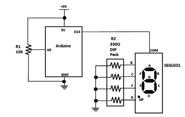
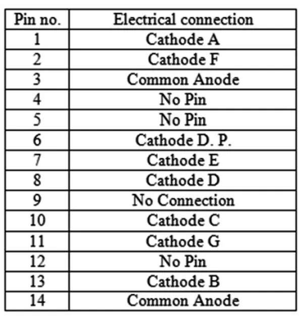
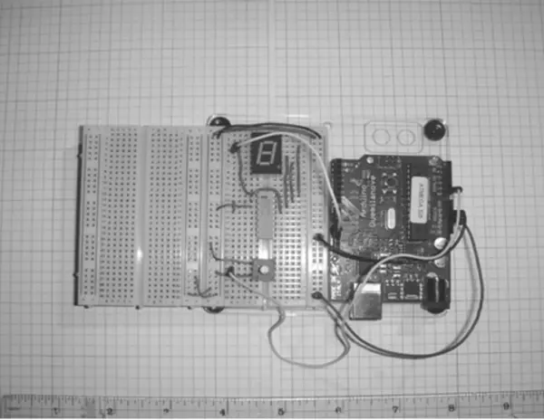
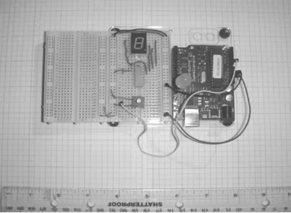
For setting up the common anode seven-segment LED display as depicted in the circuit schematic diagram, the pinout is illustrated in Figure 2-22. Note that some pins are omitted; this should not be mistaken for a defective or faulty seven-segment LED display. Constructing the complete Arduino Flasher-Tester circuit is straightforward on a compact solderless breadboard, as exemplified in Figure 2-23. Adding an element of amusement, a large blue LED can be integrated into the circuit assembly, as showcased in Figure 2-24. Tweaking the potentiometer to achieve a rapid flash rate imparts a stroboscopic effect to the blue LED.
The Arduino community boasts a substantial size, with contributors consistently introducing fresh sketches and tutorials on a daily basis. The flashing control sketch featured in Listing 2-2 originates from this community of dedicated volunteer software developers and contributors.
Listing 2-2. The Arduino Seven-Segment LED Flasher-Tester’s Potentiometer LED Control Sketch
/*
Analog Input
Demonstrates analog input by reading an analog sensor on analog pin 0 and
turning on and off a light emitting diode(LED) connected to digital pin 13.
The amount of time the LED will be on and off depends on
the value obtained by analogRead().
The circuit:
* Potentiometer attached to analog input 0
* center pin of the potentiometer to the analog pin
* one side pin (either one) to ground
* the other side pin to +5 V
* LED anode (long leg) attached to digital output 13
* LED cathode (short leg) attached to ground
* Note: because most Arduinos have a built-in LED attached
to pin 13 on the board, the LED is optional.
Created by David Cuartielles
Modified 4 Sep 2010
By Tom Igoe

This example code is in the public domain.
http://arduino.cc/en/Tutorial/AnalogInput
*/
int sensorPin = A0; // select the input pin for the potentiometer
int ledPin = 13; // select the pin for the LED
int sensorValue = 0; // variable to store the value coming from the sensor
void setup() {
// declare the ledPin as an OUTPUT:
pinMode(ledPin, OUTPUT);
}
void loop() {
// read the value from the sensor:
sensorValue = analogRead(sensorPin);
// turn the ledPin on
digitalWrite(ledPin, HIGH);
// stop the program for < sensorValue > milliseconds:
delay(sensorValue);
// turn the ledPin off:
digitalWrite(ledPin, LOW);
// stop the program for < sensorValue > milliseconds:
delay(sensorValue);
}
As discussed earlier, the potentiometer provides the analog-to-digital count (ADC) values using this line
of instruction:
sensorValue = analogRead(sensorPin);
The Arduino pin used to obtain the potentiometer- control voltage levels is A0. Based on the ADC value,
the sketch produces a delay that corresponds to the flash rate using this line of instruction:
delay(sensorValue);
Pin D13 is driven LOW based on this line of instruction and the one that follows:
digitalWrite(ledPin, LOW);
The flash rate remains at the specified switching value until the potentiometer’s resistance is changed.
The 7447 BCD-to-Decoder IC Basics
In the ultimate version of the Mini Digital Roulette game, a distinct integrated circuit (IC) is utilized, designed to receive a four-bit binary input and translate it into its corresponding decimal counterpart. Employing a binary weighted value system of 8-4-2-1, this setup facilitates the display of numbers 0 through 9 on a seven-segment LED display. The four inputs, designated by the letters D, C, B, and A, can be transformed into numerical representations ranging from 0 to 9. Figure 2-25 provides an illustration of the seamless conversion of four-bit binary values into their equivalent decimal form, known as Binary Coded Decimal (BCD).
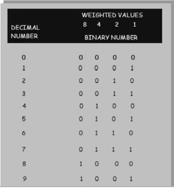
Take note that D corresponds to 8, C corresponds to 4, B corresponds to 2, and A corresponds to 1. By incorporating any value associated with a binary value of 1, achieving numbers from 0 to 9 can be effortlessly accomplished.
Example: Convert binary 1001 to its equivalent decimal number.
Solution:
Step 1 involves examining the weighted values within the BCD-to-decimal converter table and gathering the numbers that possess a “1” beneath them.
8 and 1 have a binary value of 1
Step 2. Add the weighted values together.
8 + 1 = 9
Hence, binary 1001 corresponds to the decimal value 9. It truly is that straightforward!
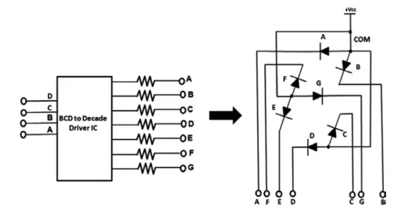
Through the 7447 BCD-to-Decoder driver circuit, the appropriate segments of the seven-segment LED display can be illuminated in accordance with the binary four-bit data value detected at its input pins. The uncomplicated diagram featured in Figure 2-26 delineates the binary coded decimal inputs as well as the seven-segment outputs of the 7447 BCD-to-Decode driver IC, facilitating the activation of a seven-segment LED display.
Build a BCD-to-Decimal Circuit with Seven Segment LED Display
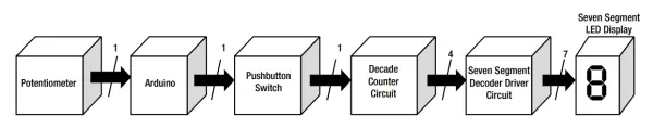
Presently, an enhancement can be introduced to the Mini Digital Roulette game by adopting a seven-segment LED display, offering improved number visibility for players as compared to the LED bar display. The driving of segments within this setup relies on the 7447 IC, which responds to a four-bit binary count value originating from its input pins. To generate the essential four bits for the BCD-to-Decoder driver chip, a 7490 Decade Counter IC is employed. This 7490 Decade Counter effectively generates a maximum of ten count states, leveraging the four-bit binary pattern illustrated in Figure 2-25. The Arduino serves as the source of the digital clock signal, essential for incrementing the count values to be presented on the seven-segment LED display. Referencing Figure 2-27, the circuit schematic diagram for the BCD-to-decimal circuit incorporating the seven-segment LED display is depicted.
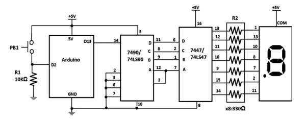
Pressing the momentary tactile switch PB1 initiates the counting sequence, commencing from 0. The highest count exhibited on the seven-segment LED display is 9, and the counting sequence perpetually cycles through this range.
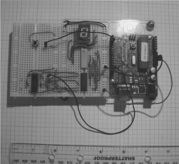
Assembly of the Final Circuit on the Breadboard
Figure 2-28 illustrates the construction of the enhanced Mini Digital Roulette game. As emphasized in Chapter 1, ensuring appropriate lengths for components and jumper wire leads contributes to a tidy circuit arrangement. To achieve orderly wiring, it’s advisable to position the components on the solderless breadboard in a manner that facilitates optimal jumper routing. In line with this strategy, an extra mini solderless breadboard was utilized for accommodating the other IC components, yet the overall circuit dimensions remained manageable, as depicted in Figure 2-28.
Adding the Mini Digital Roulette Game Software
Listing 2-2 displays the script for enhancing the Mini Digital Roulette game. The pivotal aspect of implementing this script centers around utilizing pin 13 on the Arduino computing platform, designated for clocking both the counter circuit and the seven-segment LED display. The pace at which the game progresses is governed by the ensuing line of instruction:
int blinktime = 20;
delay(blinktime);
Through alteration of the integer value within the “blink time” variable, the delay instruction will generate the necessary pulsating switching required to operate the 7490 and 7447 digital ICs. As an exploratory endeavor, partake in crafting diverse switching patterns and document the ensuing outcomes by adjusting the value of the “blink time” variable.
Final Testing of the Mini Digital Roulette Game
Within this chapter, I delineated a product development methodology that transforms the Arduino into an educational instrument for comprehending electronics. As established in the preceding sections, every interface circuit and output driver component can undergo examination with fundamental electronics testing tools like a DMM and oscilloscope. Upon the successful functioning of each sub-circuit, the ultimate testing phase (with the Arduino sketch uploaded) entails verifying the correct output responses of the final product.
In the scenario of the Mini Digital Roulette games, the rate at which alterations occur in the displayed data on both the LED bar and seven-segment LED displays relies on specific directives designed to generate delay-based clock pulses. When conducting tests, a critical aspect to note is the unpredictability of the numbers exhibited upon game completion. It is essential to ensure that identical numbers are not concurrently showcased on both visual displays. Furthermore, careful attention should be paid to the speed at which the game concludes and this should be adjusted accordingly. A game that concludes swiftly may fail to retain the player’s engagement. Conversely, if the device takes an extended time to come to a halt, the player’s interest could wane. Timing holds paramount significance.
Should the segments on the seven-segment LED display show interruptions, it is advisable to scrutinize the wiring to confirm proper connectivity of IC pins to the optoelectronic component. Additionally, a review of the sketch inputted into the Processing Editor should be conducted to identify any typographical errors that could potentially lead to improper operation of the Arduino.
Further Discovery Method Suggestions
In order to sustain the thrill of delving into electronics with Arduino, I propose the incorporation of a potentiometer, enabling the player to fine-tune the pace of the game’s execution. Figure 2-29 illustrates the block diagram outlining this fresh addition to the game’s mechanics. Upon pressing the button, the game is set into motion, incrementing the count values on the seven-segment LED display. Releasing the button prompts the optoelectronic device to reveal a displayed number.
Depressing and subsequently releasing the button ought to unveil a distinct number on the seven-segment display. Engaging in a self-discovery endeavor entails devising a circuit schematic diagram based on the system block diagram depicted in Figure 2-2. The sketch provided in Listing 2-1 can be employed to evaluate the functionality of this novel circuit design.
- What does the Arduino detect to start the LED roulette game?
The Arduino detects a rising edge from a push-button switch (0V to +5V) to start the game. - How is the Arduino input held low before the button is pressed?
A 10K pulldown resistor is used in series with the push-button to ensure a valid logic 1 is detected on rising edge. - How many LEDs are sequenced in the LED bar version described?
The sketch sequences three LEDs connected to digital output pins 8, 11, and 13. - How is a single LED forward current calculated in the example?
Using IFD = (V1 - VFD) / R1 with V1=5V, VFD=1.66V, and R1=330 Ω yielding ~10.12 mA. - How can the LED sequence visual effect be changed?
Modify the lightpins array in the sketch, for example int lightpins[3] = {8,11,13}, to change LED order. - What component converts four-bit binary to seven-segment outputs?
The 7447 BCD-to-decoder (7447/74LS47) drives the seven-segment display from four-bit BCD inputs. - How are the four bits for BCD provided in the final version?
A 7490 decade counter (7490/74LS90) generates the four-bit count values for 0–9. - How is the game speed adjusted in the flasher-tester and roulette sketches?
By changing a blink time delay variable or using a potentiometer read via analogRead to vary delay(sensorValue). - What should you check if seven-segment segments flicker or are missing?
Inspect wiring to ensure IC pins are correctly connected to the display and verify the uploaded sketch for typographical errors. - How is testing of LED bar or seven-segment segments performed with a DMM?
Use the diode or ohmmeter mode: red lead to anode (or common anode for seven-segment) and black to cathode; a functional segment will illuminate due to the meter's small current.