Summary of Crazy Circuits: an Open Source Electronics Learning System
Crazy Circuits is an open-source, low-cost modular electronics system designed to teach STEM concepts using LEGO bricks. It eliminates the need for soldering and complex breadboards by utilizing custom PCBs and conductive tape. The system integrates with existing LEGO environments, supports 3D circuit building, and scales from basic circuits to programming. By making designs public, it empowers users to create their own parts while maintaining a fun, educational experience for both children and adults.
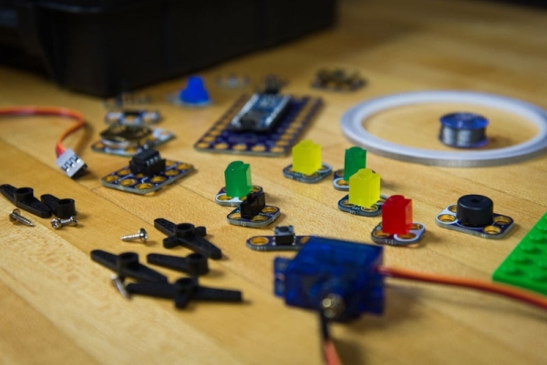
Parts used in Crazy Circuits:
- Custom PCBs
- LEGO bricks (including Technic line)
- Nylon Conductive Tape (Maker Tape)
- Conductive thread
- Copper foil tape
- LEDs
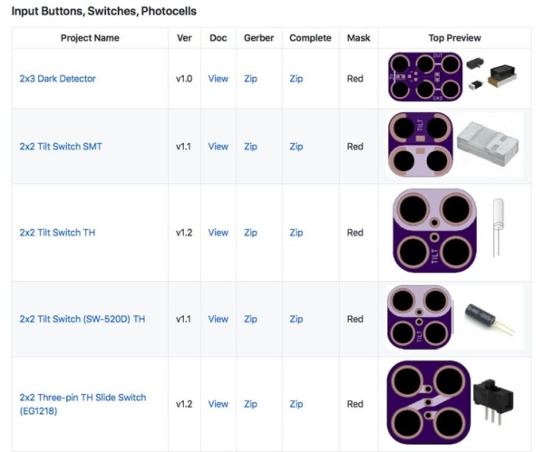
- Switches
- Battery holders
- Through hole components
- KiCad software
The education and home market is flooded with modular electronics ‘learning’ systems designed to teach kids and adults key STEM and STEAM concepts. Products such as LittleBits or Snapcircuits seem to dominate every holiday gift guide or parent blog for educational toys. However, these systems always come with a hefty price tag attached and many feel more like toys than learning tools.
About three years ago we started started designing Crazy Circuits as a low cost, reusable, modular, non-soldering, fun, system that could be used as an actual learning tool. We wanted something that parents and teachers could easily integrate with kits they already had or inexpensive off the shelf components. Something for both the Maker Community to enjoy as well as the average adult.
In the end Crazy Circuits was everything we hoped for and more. The system worked flawlessly with any LEGO based environment, could easily be used with conductive thread for sewing, and easily scaled from simple circuits up through basic programming. Oh, and it was fun to use as well which made all our lives easier.
In this write up we’re going to show you how we designed Crazy Circuits components, our curriculum, how you can make and design your own parts, and ways that Crazy Circuits works with other systems.
Full disclosure: We do sell Crazy Circuits parts and kits, however you can easily use our Open Source files to get your own boards made up or design your own parts. You can use this system for all kinds of things and never send us a single penny.
Give Aways: We’re trying something new in 2019. We’re giving away free parts and kits to people (US Residents only) who follow us on instructables, facebook, instagram, and youtube. Most likely we’ll be giving away a couple of full kits, finished parts, and blank PCBs. Just follow or subscribe and we’ll start giving away stuff.
Step 1: Philosophy Behind Crazy Circuits
When I was a teacher I was really annoyed that I couldn’t afford fancy electronics systems for my classroom, even though every teaching conference or inservice I attended kept recommending them. I just didn’t have a budget for a $100 kit that came with five parts and at best would keep three students occupied for five minutes. I ended up doing what most science teachers do and just bought cheap raw parts off eBay and Amazon but that required me to do a lot of new lesson planing and activity design work. I also found that my younger students had a hard time wrapping their head around breadboards.
I eventually was able to get some funding to buy some LittleBits kits for use with my after school science club. They were fun to use (and to be honest, a well put together system), but when I asked my middle school students to explain how they worked I received my favorite answer of the year “I don’t know, magnets?”. These were kids who had been building some complicated circuits weeks earlier, yet LittleBits came off as more of a toy than anything else.
When we started brainstorming a modular system we wanted to make sure that students were aware of HOW parts were interacting and were then able to draw parallels to common parts. We also knew that we needed something akin to a breadboard, yet easier to wrap their heads around than an actual breadboard. We also had to make it fun and engaging.
Challenge accepted!
Step 2: Why LEGO?
Everything came together thanks to LEGO. It’s a natural grid based system which allows us to make logical and easy to understand circuits. It’s inexpensive, readily available, and it’s very fun. You’d be hard pressed to find someone who hasn’t used LEGOs before or a kid who doesn’t have LEGOs in their life.
On the most basic level we realized that adding lights and basic motion to LEGO was something that was appealing to kids (and adults) of all ages. Thanks to years of licensed properties most kids had LEGO kits that begged to have lights on them. We quickly started looking on Craigslist and Facebook Marketplace for second hand LEGO Star Wars kits for us to play with… and also to add some Crazy Circuits parts to.
But from a technical perspective LEGO allowed for a 3D building environment with lots of room to be creative. Circuits in the real world are often 3 dimensional and we wanted to show kids that they too can make 3D circuits with ease. The Technic line of LEGO takes things a step further when you factor in gears and mechanics. Now we could easily build a LEGO tank and make it interactive without too much work.
LEGO just made sense.
Step 3: Designing PCBs & Making Your Own
From the get go we knew we wanted to make this system Open Source. Once we started actually designing things we realized that it would be stupid NOT to make it Open Source since the system was so darn simple. You can find all our PCB designs on our GitHub Repo as well as some information for designing your own parts.
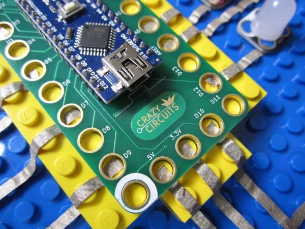
The most difficult process was getting the hole spacing just right. LEGO parts are 99.99999999% identical, but we knew that we’d need to add some wiggle room. More or less we designed up a bunch of PCBs with super minor adjustments in hole sizing and tested them out. Kind of similar to how optometrists test out glasses on people. The annoying part was us realizing that PCB manufacturing is never 100% correct, that there is a small margin of error. We decided to err on the side of caution and make our PCB holes larger than necessary.
You can design your own parts using the free KiCad software and our Library, then get the parts made up using such services such as OSHPark. We have some development notes in our Repo, but it’s probably best to just take an existing part and modify it. We did make up many more parts than necessary for this project and most simple through hole components will fit onto one of our generic boards.
Our PCB designer wanted us to point out his top tips for making up parts.
- It’s best to take an existing module and edit it.
- The Lego holes are 4.98mm diameter after plating.
- Minimum total Lego hole total annular ring diameter is 6mm.
- Use white silk for ground or ‘pin 2’ polarity markings where needed.
- Circuit kits use 2×2 snappable support tabs with 20mil drills and 6 mil traces.
- Grid size should be 8mm. Holes should be centered on grid lines.
- A footprint origin point (0,0) should be on the lower leftmost Lego hole.
- Remove mask openings on the top of the board.
- In particular, leave 30 mils of solder dam between a pad and a plated hole.
- When necessary, leave the Lego holes unplated and place a via.
Step 4: Conductive Tape Is the Key
Lastly we had to figure out how to connect everything together. We immediately decided we hated the idea of wires and alligator clips; it took away from the simplicity of everything. We liked using conductive tape but the copper foil tape was impossible to use. We could get the tape down but it wouldn’t come back up again. We even tried using conductive thread but that proved to be impossible to control. After a lot of hours on Skype with a tape factory in China we manufactured some custom Nylon Conductive Tape (Maker Tape) which was strong enough to peel back up again, yet inexpensive enough to be competitive with common copper foil tape.
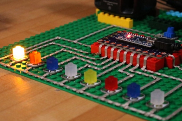
Thanks to the fact that we had a whole lot of test PCBs with different sized holes sitting in our workshop, we were quickly able to find a size spacing that allowed us to make a pressure fit using the Nylon Conductive Tape. In this way students HAD to end their tape at a specific spot: they had to actually take time and design their circuit. This aspect allowed us to turn Crazy Circuits into a learning tool, not just a toy.
Using 1/8th inch tape also had the weird side benefit of allowing for two layer circuits. Normally we’d lay the tape over the TOP of the LEGO studs, but the 1/8th inch tape also worked perfectly for also going BETWEEN the LEGO studs. People could make all kinds of complicated circuits using tape on LEGO. (Though a bit awkward. If nothing else it allowed students to ‘jump’ an existing line with only a little bit of effort.)
A basic example circuit might use a switch, battery holder, and an LED. For all our parts we used white silk screening to designate the GND (Negative) poles and the colored side to indicate the Positive poles. The above video shows me making a simple circuit. Lay down tape, pressure fit on parts, add power.
Source: Crazy Circuits: an Open Source Electronics Learning System
- Why was Crazy Circuits created?
It was designed as a low-cost, reusable, non-soldering learning tool that avoids the high price tags of other systems. - How does the system integrate with LEGO?
The custom PCBs fit into the LEGO grid system, allowing users to build 3D circuits and add lights or motion to LEGO sets. - What is the key component used for connections instead of wires?
Nylon Conductive Tape, also known as Maker Tape, is used to connect parts through a pressure fit method. - Can users design their own parts for this system?
Yes, the project is open source, and users can design parts using KiCad software and the provided library. - What are the specific dimensions for the LEGO holes on the PCBs?
The Lego holes have a diameter of 4.98mm after plating, with a minimum total annular ring diameter of 6mm. - How are positive and negative poles indicated on the parts?
White silk screening marks the GND (Negative) poles, while the colored side indicates the Positive poles. - Is it possible to create two-layer circuits with this system?
Yes, the 1/8th inch tape allows for two-layer circuits by laying tape between LEGO studs as well as over them. - What software is recommended for designing new modules?
The article recommends using the free KiCad software along with the Crazy Circuits Library.