Summary of Battery Reconditioner using an Arduino
This article details a DIY battery reconditioner project designed to revive dead or weak rechargeable AA and AAA batteries using an Arduino. The author repurposed an old Panasonic charger's PCB for the battery holder and utilized relays with specific resistors to discharge batteries in two stages: a fast discharge from 1.2V to 1.0V, followed by a slow discharge down to 0.4V before recharging. The project successfully overcame issues with transistor-based designs that failed at low voltages.
Parts used in the Battery Reconditioner:
- Arduino clone (Really Bare Bones Board)
- Arduino USB interface
- 2 Relays (G2RL-24DC5)
- 2 2N3904 transistors
- 8 1.6 Ohm 1W resistors
- 2 10K resistors
- 1 3.3K resistor
- 2 IN4001 diodes
- Old Panasonic battery charger (for PCB and housing)
- Solder wick and soldering iron
So if you are like this Lazy Old Geek, you have a lot of rechargeable batteries lying around. I wrote another Instructable with some battery tips.
http://www.instructables.com/id/Rechargeable-Battery-Tips/
Amongst these batteries, I have a lot that no longer work or don’t work very well. So I decided to try to revive them.
First step: If the battery isn’t totally dead, stick it in something like a flashlight, turn it on and let it run until it stops working. Try to recharge and see if it works better. I tried this with a couple of cordless drill batteries and was able to ‘restore’ the battery packs.
Second step: However, I have a lot of AA and AAA batteries that still didn’t work. I also have a bunch of battery chargers but none of them will recondition batteries very well, so I decided to make my own.
Well, after years of diligent research (well, actually it was more like days and not very diligent), I decided this method had the most promise:
http://batteryuniversity.com/learn/article/how_to_restore_nickel_based_batteries
Okay for the technically challenged, the basics are:
1. Fast discharge the battery from 1.2-1.4 volts, down to 1 volt.
2. Discharge it slower to about 0.4 volts. Then recharge and see if it works.
This may have to be repeated several times.
Step 1: Design Battery Holder
My Design criteria for a battery reconditioner:
Individual circuits for each battery.
Discharge up to 3000mA AA batteries.
Do up to four AA or AAA batteries at a time.
So, since I’m an Arduino Geek, I decided to use an Arduino.
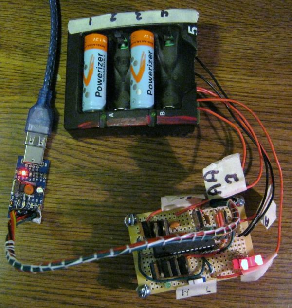
But first, I needed a holder for AA and AAA batteries. Well, I didn’t have any readily available and didn’t want to try to make my own (as seen in many Instructables). But I did have an old Panasonic battery charger that I didn’t really like (See rechargeable battery tips). This one will take AA or AAA batteries.
So I took a screwdriver and opened it up. (see picture). All of the battery contacts are on the PCB. So I took my trusty $4 soldering iron and some solder wick and removed most all of the components.
Now I don’t expect very many readers will have one of these around but you can probably make or buy suitable battery holders. So I’m not going to go into a lot of details about how I modified the PCB. Here is the design criteria for my battery holder:
All the grounds (the – sides of the batteries) are tied together.
My battery slots can take either AA or AAA batteries. The positives for each slot type can be tied together.
So six wires will come off the holder: two black grounds and four red positives. I labeled the positives for each slot.
This Panasonic charger actually charged in pairs so that you had to charge two or four batteries at a time. So I had to do some cuts on the PCB. Then I also had to jumper the AA and AAA positives together for each slot.
Caution: The wire I used is 22AWG. 22AWG is rated for 7 Amps (7000mA) so will handle the currents for 3000mA discharge rate. Since I will have up to four batteries at a time, I have two ground wires. Make sure your wiring can handle the current.
I cut up the housing and labeled the battery slots. (see pictures)
Step 2: First/Second Designs
So my first design was using TIP122 Darlington transistors to discharge the batteries. I also purchased some ICs to measure the current so that I could discharge the batteries at the proposed ‘1C’ rate which is 3000mA for 1 hour. I selected the TIP122 because it can handle 5A (5000mA) continuous.
But I couldn’t get these to work. I think the main problem is that when drawing 3000mA, the ‘On’ voltage is over 1 volt. So if the battery voltage is only 1.2 volts, there is not enough difference for the TIP122 to work.
Failed: First design
My Design 2 was to use 5 volt relays to connect resistors to discharge the batteries. Now this actually worked and I will provide information in case you might want to try this method.
Now I only have two relays but these are DPDT relays so I could control two circuits with one relay. With this limitation, I could only discharge two batteries at one time.
Stage 1: Fast discharge from 1.2 Volts to 1.0 volts at ‘1C’. For a 3000mA battery, this is about 3000mA (3A) discharge. Okay this is a simple application of Ohm’s Law, E=IR. Since we know the voltage and the current, we can figure the resistance. R=E/I = 1.2/3 = 0.4 Ohms.
Caution: You also have to watch out for power. P=IE = 3*1.2 = 3.6 Watts. Most little resistors are ¼ Watt and would burn up. So you need higher wattage resistors.
Stage 2: Slow discharge from 1.0 Volts to 0.4 volts over a couple of hours. Unfortunately, they didn’t give a discharge current. But I made an educated guess and decided to use ‘½ C.’
So in theory, back to Stage 1, I need a 0.4 ohm 3.6 Watt(or higher). Okay, these might be available but I went a different way. If you have two resistors in parallel, their resistance is divided by two and by the way, the wattage doubles. (See pictures)
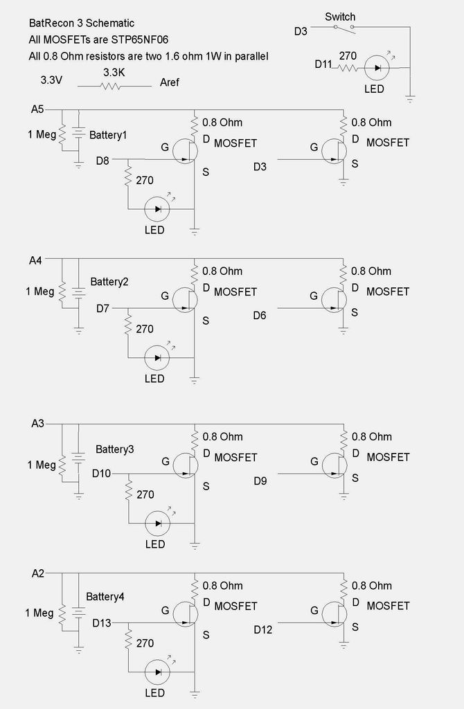
So a fairly easy to get resistor is 1.6 Ohm 1 Watt. If you put two in parallel, that is 0.8 Ohm 2 Watt. If you put four in parallel, that is 0.4 Ohms, 4 Watts. Perfect. Since I am very clever, I decided to use two relays with 0.8 Ohms for each relay for each battery. So when both relays are on, the resistance for each battery is 0.4 Ohms. See schematic.
FYI: These relays can handle 8 Amps per contact and the contact resistance is 100 milliOhms or 0.1 Ohms maximum. Actually, this adds a little as each circuit could be up to 0.9 Ohms and two in parallel would be 0.45 Ohms but that’s close enough.
So for stage 1, I turn on both relays and discharge at around ‘1C’ 3000mA. When the battery voltage drops to about 1 Volt, then for stage 2, I turn on only one relay so it discharges at a slower rate until the battery drops to about 0.4 volts.
Now, I am not going to explain the point to point wiring for this circuit is rather extensive. Hopefully, you should be able to figure it out from the schematic in the picture.
Here’s some basic guidelines:
For this version of RBBB, I added male header pins sticking out the bottom of the PCB so that it will plug into a breadboard. I made a little template with Excel to identify pins and match them up to my breadboard. See picture.
This breadboard has a + and a – rail on both sides so I connected grounds and +5 volts to both rails.
More details on using the G2RL-24DC5 are available in my Instructable:
http://www.instructables.com/id/Arduino-Remote-Control/
Schematic comments:
The 1N4001 diodes across the relays are for back EMF. I think they helped reduce glitching when the relay turns on and off.
The 1 MegOhm resistors across the battery are so that the software can tell that there is no battery installed (if there is no battery installed). Any resistor from about 10K to 10M should work fine.
Parts list Design 2:
Arduino clone: Really Bare Bones Board (RBBB) ~$5
Arduino USB interface ~$5 (or USB-BUB)
http://www.instructables.com/id/Arduino-USB/
2 Relays: Digikey Z146-ND (G2RL-24DC5) $3.22 (Digikey.com)
2 2N3904 transistors $ 0.02 (TaydaElectronics.com)
8 1.6 Ohm 1W resistors $ 0.30 (ebay cn-resources)
2 10K resistors
1 3.3K resistor
2 IN4001 diodes
Step 3: Design 2 Software
This is mostly electrical theory and can be skipped by all you practical readers.
Problem: So when I turned on the relays starting to discharge the battery, the battery voltage drops down. For Stage 1, I am looking for the voltage to drop to 1 Volt but it will do this too quickly.
Cause: The problem is something called battery internal impedance. A battery is not an ideal voltage source (there is actually no such thing in the real world). It has something called internal impedance that can be represented as a resistor as shown in the picture. So the battery voltage and the internal impedance, Ri on the left side of the picture are what the battery looks like electrically. So when the battery is connected to a load, it actually connects the internal impedance in series and makes a voltage divider circuit. Normally this is not a problem as the load resistance is much higher than the internal impedance so the internal impedance is insignificant. However, with a 0.4 ohm load, the internal impedance can become significant.
For more detail: Battery Reconditioner using an Arduino
- How can I revive batteries that no longer work well?
Discharge them quickly from 1.2 to 1.4 volts down to 1 volt, then discharge slower to about 0.4 volts before recharging. - What design criteria were used for the battery holder?
The holder needed individual circuits for each battery, the ability to discharge up to 3000mA, and capacity for four AA or AAA batteries at once. - Why did the first design using TIP122 transistors fail?
The On voltage was over 1 volt, which meant there was not enough difference when the battery voltage dropped to 1.2 volts for the transistor to work. - How are the resistors configured for Stage 1 of the discharge?
Four 1.6 Ohm 1 Watt resistors are placed in parallel to create a 0.4 Ohm resistance capable of handling 4 Watts for the fast discharge. - What is the purpose of the 1 MegOhm resistors across the battery?
They allow the software to detect if no battery is installed by checking for a reading between 10K and 10M ohms. - Can this device handle AA and AAA batteries simultaneously?
Yes, the design allows for up to four AA or AAA batteries to be processed at the same time. - What type of wire was used and why?
22AWG wire was used because it is rated for 7 Amps, ensuring it can handle the high currents required for the 3000mA discharge rate. - Why were diodes added across the relays?
The 1N4001 diodes were added to reduce glitching caused by back EMF when the relay turns on and off.