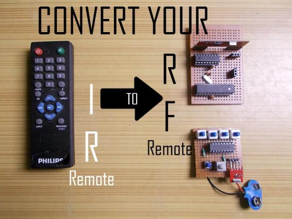
In today’s Instructable, I’ll show you how you can use a generic RF module without a microcontroller which will eventually lead us to build a project where you can convert an IR Remote of any device to a RF Remote. The main advantage of converting an IR Remote to RF, is that, you don’t have to point the remote before pressing the buttons for the device to work. Also, if you have a device that is not always in range of the remote, like a home theater in the corner of a room, this RF Remote will make your life easier.
Let’s get started.
Step 1: How About a Video?
The videos has all the steps covered in detail required for building this project. You can watch it if you prefer visuals but if you prefer text, go through the next steps.
Also if you want to watch the project in action, refer the same video.
Step 2: Parts List.
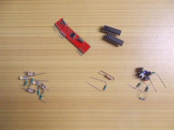
RF Module:
INDIA – https://amzn.to/2H2lyXf
US – https://amzn.to/2EOiMmm
UK – https://amzn.to/2EOiMmm
Arduino:
INDIA – http://amzn.to/2FAOfxM
US – http://amzn.to/2FAOfxM
UK – http://amzn.to/2FAOfxM
Encoder and Decoder ICs:
INDIA – https://amzn.to/2HpNsQd
US – Encoder –> https://amzn.to/2HpNsQd ; Decoder –> https://amzn.to/2HpNsQd
UK – Encoder –> https://amzn.to/2HpNsQd ; Decoder –> https://amzn.to/2HpNsQd
TSOP IR Receiver –
INDIA – https://amzn.to/2H0Bdu6
US (Receiver and LED) – https://amzn.to/2H0Bdu6
UK (Receiver and LED) – https://amzn.to/2H0Bdu6
IR LED:
INDIA – https://amzn.to/2GZ17y9
Step 3: Encoder and Decoder.
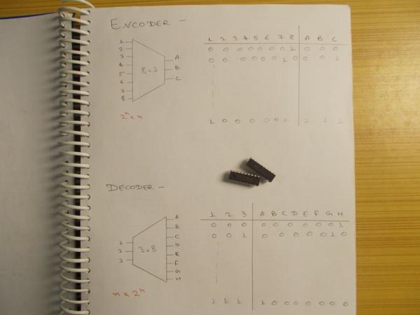
To use them without microcontroller you’ll need two ICs. They are called encoders and decoders. They are basic combinational circuits. Encoder has more inputs than the number of outputs. Looking at the truth table we can see that the three output pins have different combination for different states of input pins. Generally the input output pins of the encoder is defined as 2^n x n, where “n” is the number of bits. Decoders are just the opposite of the encoders and they have the pins descriptions like n x 2^n. If you ask what will happen if more than one pin goes high at the same time, then I’ll say it is beyond the scope of this Instructable.
The encoder and decoder ICs we will be using are HT12E and HT12D, D for decoder and E for encoder. Let’s take a look at the pins of these ICs.
In HT12E, pin numbers 10, 11, 12 and 13 are data input pins and pin 17 is the output pin, which we will modulate. Pins 16 and 17 are for internal RC oscillator and we connect a resistor ranging from 500k to 1M (I used 680k) across these pins. Actually, the resistor connected will be a part of the RC oscillator. Pin 14 is transmit enable pin. It is an active low pin and the data will be transmitted only if this pin is held low. Pin 18 and 9 are Vcc and GND respectively, and I will talk about remaining eight pins in a while.
Things are somewhat similar for the decoder. 18 and 9 are supply pins, 15 and 16 are internal oscillator pins and a 33k resistor is connected between them. Pin 17 is the valid transmission pin of the IC which is goes high whenever a valid data is received. The modulated data is given to pin 15 and decoded parallel data is obtained from pins 10, 11, 12 and 13.
Now you will notice that decoder IC also has those 8 pins that we saw in encoder. In fact, they serve a very important purpose in keeping your transmission secure. These are called address setting pins and they ensure that the data sent is received by the right receiver in an environment where there are more than one of these pair. If in the encoder, all of these pins are held low, then to receive the data all of these pins of the decoder must also be held low. If four are held high and four are held low, decoder address pins must also have the same configuration, then only the data will be received by the receiver. I will be connecting all pins to ground. You can do whatever you like. For changing the address on the go, a DIP switch is used, which connects the pins to either high or low just by a flick of the buttons on it.
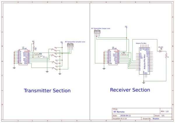
Step 4: Prototyping.
Enough theory, let’s go ahead and try it practically
You will need two breadboards. I went ahead and connected all up using the circuit diagram in this step with LEDs in place of the Arduino and push buttons with a 10k pull down resistor in place of switches.. I used separate power supplies for both of them. As soon as you power the transmitter, you will see that the valid transmission pin goes high indicating that the successful connection is made. When I press any button on the transmitter side, the corresponding LED on the receiver side glows. Multiple LEDs are turned on if I press multiple push buttons. Notice the VT led, it blinks every time it receives a new data, and this will be very helpful in the project we are going to make.
If your circuit is not working, you can debug easily just by connecting the output of encoder to input of decoder and everything must still work the same. This way you can at least make sure that you ICs and its connections are alright.
If you change one of the address pins to high, you can see everything stopped working. To make it work again, you can either connect it back, or change the same pin status on the other side to high. So, keep this in mind while designing anything like this as they are very important.
Step 5: Infrared.
Now let’s talk about infrared. Every IR remote has an IR led at its front and pressing the buttons on the remote make that led light up which can be seen in the camera but not with naked eye. But it’s not that easy. The receiver must be able to distinguish each button pressed on the remote so that it can perform the said functions. To do that, the led is lighten up in pulses having different parameters and there are various protocols that manufacturers use. To learn more, refer the links I have provided.
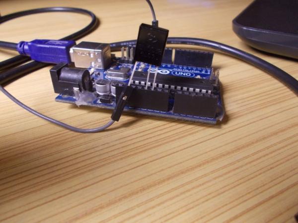
You might have guessed by now that we are going to mimic those IR codes of the remote. To get started we will need an infrared receiver like TSOP1338 and an Arduino. We are going to determine the hex codes of each buttons that make them different from the other one.
Download and install the two libraries, link of which is provided. Now open IRrecvdump from IRLib master examples folder and upload it to Arduino. First pin of the receiver is ground, second is Vcc, and third is output. After applying power and connecting output to pin 11, I opened serial monitor. I pointed the IR remote to the receiver and started pressing its buttons. I pressed each button twice and after I was done with all the required buttons I disconnected the Arduino.
Now look at the serial monitor, there will be lots of garbage, but they are just stray light rays that the receiver caught as it is too sensitive. But there will also be the protocol used and the is hex code of the buttons you pressed. That is what we want. So I made a note with name and their hex codes as we will be needing it later.
Links:
How IR in Remote works:
http://irq5.io/2012/07/27/infrared-remote-control-…
https://www.vishay.com/docs/80071/dataform.pdf
Libraries:
https://github.com/cyborg5/IRLib
https://github.com/z3t0/Arduino-IRremote
Step 6: What Are We Doing?
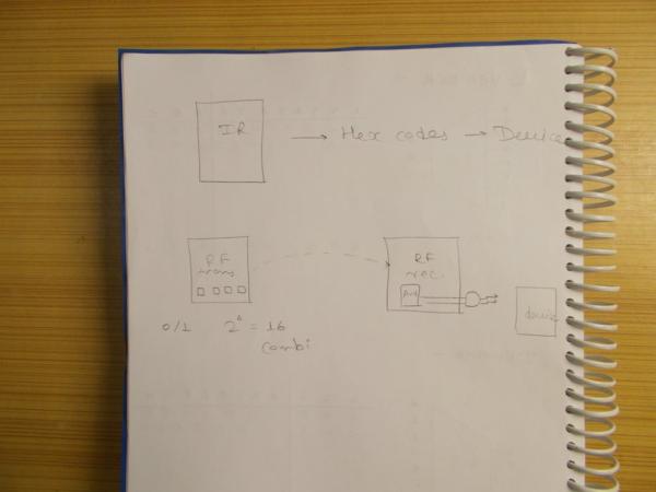
We have our IR remote of which we have determined the hex codes of the buttons of our interest. Now we will be making two small boards, one has the RF transmitter with four buttons on it that can go either zero or one, meaning 16 combinations are possible, another one has the receiver and it has a controller of some kind, in my case Arduino, which will interpret the output form the decoder and will control an IR led that eventually get the device to respond exactly the same way it did to its own remote. As 16 combinations are possible, we can mimic up to 16 buttons of a remote.
Step 7: Find the Receiver.
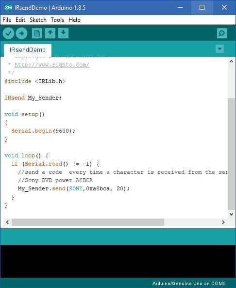
If the receiver on your device is not visible, open the IRSendDemo sketch from the library example and change the protocol and hex code accordingly. I used hex code of the power button. Now connect an IR led with 1k resistor to pin 3 of the Arduino and open serial monitor. So when you will type any character in the serial monitor and press enter, the Arduino will send the data to IR led and should cause the device to function. Hover over different regions where you think the receiver can be and eventually you will find the exact location of the receiver in your device (refer video for clear understanding).
Step 8: Soldering.
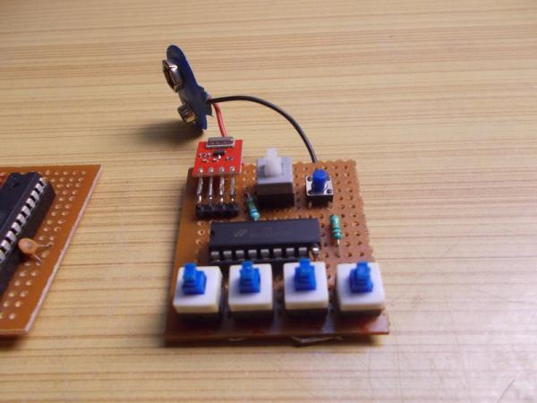
Using the same connection diagram, I built the required two PCBs, I have used standalone Arduino instead of a Pro Mini as that’s what I had laying around.
Before putting the microcontroller in, I wanted to test the connections one more time. So I applied 9 Volts to transmitter and 5 Volts to receiver and used a LED to test the functioning of the boards and quickly tested everything. I also added a power switch for saving battery to the transmitter PCB.
Finally after uploading the sketch, I fixed the Arduino to its place.
I soldered the 1k resistor directly to the cathode of LED and I will use a heat shrink before gluing it to the adapter I made for my home theatre using a GI sheet, but if you have access to 3d printer, you can build a far more professional looking adapter easily, if it is required. I will also solder a long wire between the LED and the PCB so that it is easy to place the PCB in a different place, somewhere hidden. After all these are done, it is time to test its functioning, which you can see in action in the video I have embedded in step 1.
The best thing about converting it to RF is that you don’t have to point it directly to the device you can control it even if you are on another room, the only thing you need to care about is that the RF pair must be in range and that’s it. Lastly if you have a 3d printer, you can also print a little case for the transmitter section.
Source: Convert Your IR Remote to RF Remote