Summary of Control Servo Motor Using Accelerometer
This Instructable shows how to control a servo motor position using an ADXL335 accelerometer and a NodeMCU. The accelerometer's X-axis analog output is read by the NodeMCU, mapped to 0–180 degrees, and used to drive the servo. Wiring details, Arduino IDE setup, and example code are provided to read analog values, map them to servo angles, and update the servo position in real time.
Parts used in the Control Servo Motor Using Accelerometer:
- ADXL335 Accelerometer Sensor
- NodeMCU
- Servo Motor
- Breadboard
- Jumper Wires
- Connecting Wires (optional)
- Micro USB Cable
- Computer with Arduino IDE
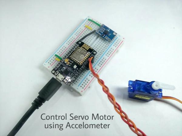
Lets begin with another cool instructable. In this Instructable we will learn how to control the position of Servo Motor using Accelerometer with NodeMCU.
Step 1: Things to Be Collected
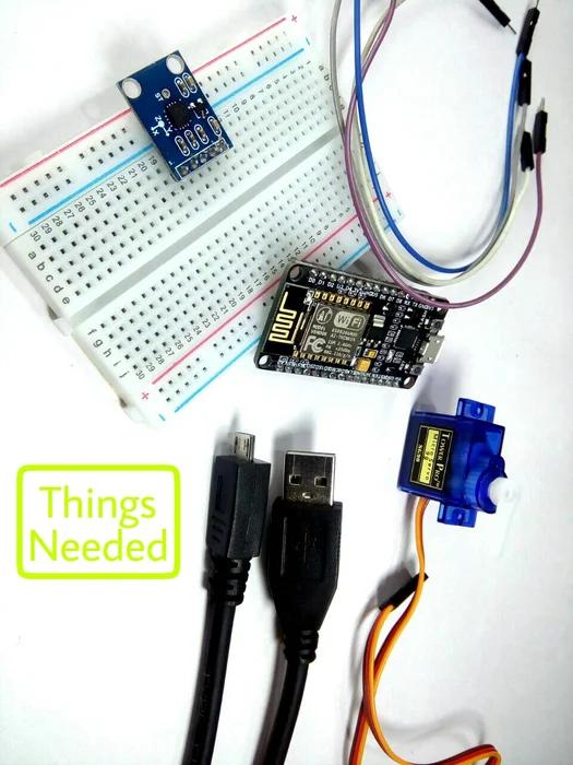
To begin with this instructable all you need is :
Hardware Requirement
- ADXL335 : Accelerometer Sensor
- NodeMCU
- Servo Motor
- Connecting Wires ( Optional )
- Bread Board
- Jumper Wires
- Micro USB Cable
Software Requirements
- Arduino IDE
Step 2: Description
Servo motors are great devices that can turn to a specified position.
Usually, they have a servo arm that can turn 180 degrees. Using NodeMCU, we control a servo to go to a specified position. As simple as that!
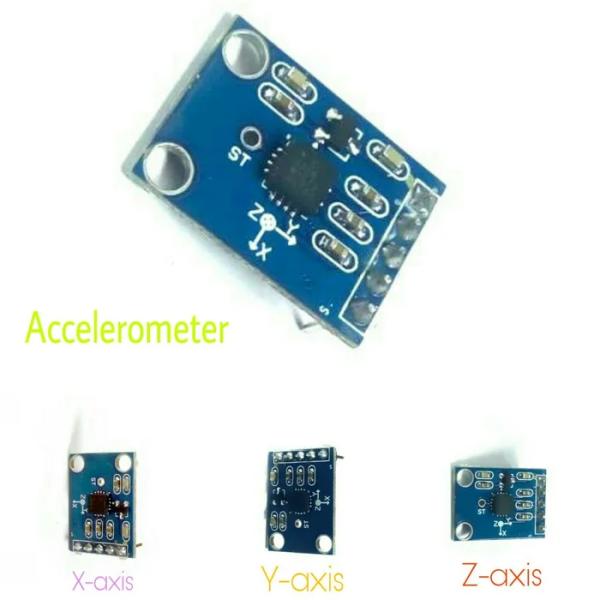
ADXL335 is 3v compatible device. It has three outputs for each axis, i.e. X, Y & Z these are analog outputs.
In my previous Instructables you would have seen how to connect a servo motor and then how to turn it to different positions and how to interface accelerometer.
If you didn’t see my previous Instructable, then you can click the link below to check those Instructables.
Interfacing Servo Motor With NodeMCU by TheCircuit
Interface Accelerometer With NodeMCU by TheCircuit
Step 3: Circuit Connections
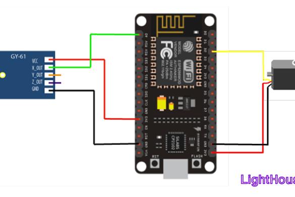
Connection to Servo
Orange wire connects to Digital Pin D2.
Brown wire connects to GND Pin.
Red wire connects to 3v3 Pin.
Connections to Accelerometer
VCC – To be connected to NodeMCU +3.3v.
X – To be connected to Analog Pin A0.
GND – To be connected to Ground Pin (GND).
To get started with coding you need to
- Download Arduino IDE
- Setup NodeMCU
Step 4: Coding Time
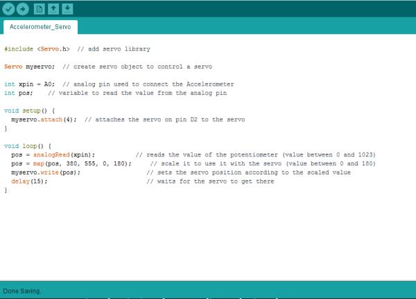
/* Control Servo Motor using Accelerometer
   By TheCircuit*/

#include <Servo.h> // add servo library which is present in Arduino IDE

Servo myservo;     // create servo object to control a servo
int xpin = A0;     // analog pin used to connect the Accelerometer
int pos;           // variable to read the value from the analog pin</p>
void setup() {
 myservo.attach(2);  // D4
}
void loop() {

  pos = analogRead(xpin);           // reads the value of the accelerometer (value between 0 and 1023)
  pos = map(pos, 380, 555, 0, 180); // scale it to use it with the servo (value between 0 and 180)
  myservo.write(pos);               // sets the servo position according to the scaled value
  delay(15);                        // waits for the servo to get there
}
Download the “Accelerometer_Servo.ino” file and open it up in the Arduino IDE.
Then Create a new sketch and paste the code below in the Arduino IDE and hit Upload.
The code will take a few minutes to upload and then you will see the servo changing angle from 0° to 180° at the interval when the accelerometer is tilted in X-axis.
You can also choose Y and Z axis by connecting to analog pin A0.
Step 5: Output Demonstration
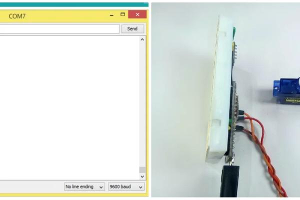
Spending a bit more time on tweaking the X-axis constants would give us a better result.
That’s it for now Makers.
Thanks for your time. Don’t forget to leave your thoughts in the comments section.
Source: Control Servo Motor Using Accelerometer
- What hardware is required to control a servo with an accelerometer and NodeMCU?
ADXL335 accelerometer, NodeMCU, servo motor, breadboard, jumper/connecting wires, micro USB cable, and a computer with Arduino IDE. - Which accelerometer axis is used in the provided example?
The X-axis is used in the example, connected to analog pin A0. - To which NodeMCU pin is the servo signal connected?
The servo signal (orange) is connected to digital pin D2 in the circuit description; the code attaches the servo to pin 2 (D4 mapping noted). - How is the accelerometer powered?
The ADXL335 VCC is connected to NodeMCU +3.3V and GND to NodeMCU GND. - What does the code do with the analog reading from the accelerometer?
It reads the analog value from A0, maps it from a 380–555 range to 0–180 degrees, and writes that value to the servo. - Which Arduino library is required for this project?
The Servo library included with the Arduino IDE is required. - Can other axes be used instead of X-axis?
Yes, you can choose Y or Z axis by connecting that axis output to analog pin A0. - How often does the code update the servo position?
The loop writes the servo position and waits 15 milliseconds before repeating.