Summary of Connecting the Electronics: Stepper Motor Control with Arduino
The article explains wiring and assembly for Stepper Motor Control with Arduino, covering wire diagrams, motor-to-controller connections, PSU wiring, soldering Electrop connector ends, Arduino interfacing (step, direction, 5V), breadboard power distribution, and powering Arduino via wall adapter or USB. It emphasizes safe practices, labeling, and modularity for syringe pump systems.
Parts used in the Stepper Motor Control with Arduino:
- Arduino (e.g., Arduino Uno)
- Stepper motors
- Motor controllers
- Power supply unit (PSU), e.g., 24V GENSSI S-350-24
- Electrop connectors
- Soldering tools and solder
- Breadboard
- Jumper wires
- 3-prong AC power cable (Line, Neutral, Ground)
- USB cable (for Arduino to computer)
- Wall adapter for Arduino
The wire diagram serves as the fundamental blueprint of the project, visually showing the pairwise connections between all components. It supports Stepper Motor Control with Arduino by clarifying how different parts
interact, helping engineers or technicians assemble the system correctly and analyze problems effectively, as it highlights all connection points.

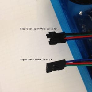
Stepper to Controller Wiring
Connecting stepper motors to their controllers enables efficient and modular control, particularly in syringe pump systems. Use Electrop connectors for easy disconnection, keeping the mechanical components inside a hood while placing the electronics outside. Clear labeling of the motor cables( A, A-, B, B-) ensures correct and safe wiring,
making the setup easier and adding flexibility in laboratory surroundings.
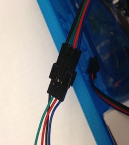
Soldering Electrop Connector Ends
A crucial first measure to increase the dependability of the Electrop connector frayed ends is soldering. For Stepper Motor Control with Arduino, it guarantees robust and long-lasting electrical connections between the stepper motors and their controllers, therefore avoiding signal loss or erratic problems caused by loose wire strands. For safe insertion into screw terminals, this process strengthens the wire tips. Clear instructions—loosen, insert, tighten—make the setup straightforward, resulting in a more stable system with fewer maintenance needs and consistent motor performance.

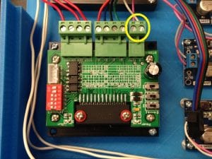
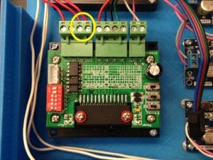
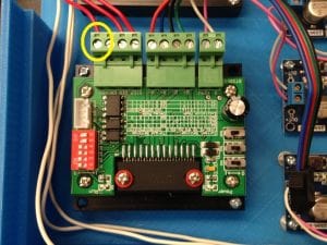
PSU to Motor Controller Wiring
The essential power connection from the PSU to the motor controller supplies the energy needed to run the stepper motors. It involves connecting +V from the PSU to +24V on the controller, and V to Ground. A voltage range of under 24V is safe; exceeding 32V risks damage. Keeping the PSU unplugged during wiring ensures safety. This setup ensures reliable motor control while protecting components from voltage issues or short circuits.
This confirms PSU-to-controller wiring by showing +24V and Ground connections, helping avoid errors and ensure safe power delivery.
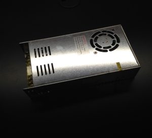
Connecting the PSU to a wall outlet provides AC power, which is then converted to DC for the motor controllers. Green is for Ground, White is for Neutral, and Black is for Line in conventional wiring. Ensuring safe system powerup and avoiding electrical dangers, a safety caution encourages users to check 3prong cable connections before plugging in.

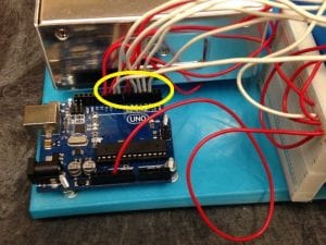
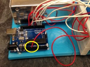
Arduino to Motor Controller Wiring
Arduino connects to motor controllers to send step and direction signals while supplying 5V power. Each controller uses three wires: step, direction, and 5V. A breadboard is recommended to split the 5V line, allowing one Arduino to control multiple syringe pumps. Odd-numbered Arduino pins connect to ‘DIR’, while even-numbered pins connect to ‘STEP’, ensuring clear, scalable, and precise Stepper Motor Control with Arduino.
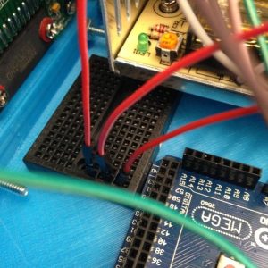
Motor Controller to Breadboard
A single wire connects the breadboard’s 5V rail to each motor controller, ensuring proper power for Arduino signal processing. This simple setup enables a modular and scalable design for controlling multiple syringe pumps.
Arduino to Breadboard
Distributing the Arduino’s 5V power to multiple motor controllers is done using a breadboard. A jumper wire connects the Arduino’s 5V output to a breadboard row, linking all points in that row. From there, five V input wires can be run to each controller. This makes troubleshooting simpler, increases scalability, and reduces wiring complexity for Stepper Motor Control with Arduino.
Arduino to Wall Outlet
Powering the Arduino independently using a wall adapter instead of relying on a computer USB connection provides consistent, standalone power. Plugging the adapter into the Arduino and a wall outlet improves system portability and allows the syringe pump setup to operate without a computer.

Arduino to Computer
The standard method for connecting Arduino to a computer uses a USB cable. This link allows code uploads, monitoring, and also powers the Arduino during development. It’s a simple and accessible way to program and test the syringe pump control system without needing a separate power adapter.

Read more: Connecting the Electronics: Stepper Motor Control with Arduino
- What is the purpose of the wire diagram?
The wire diagram visually shows pairwise connections between all components to help assemble the system correctly and analyze problems. - How should stepper motors be labeled?
Motor cables should be clearly labeled A, A-, B, B- to ensure correct and safe wiring. - Why solder Electrop connector ends?
Soldering increases reliability by creating robust wire tips for secure insertion into screw terminals and prevents frayed strands. - How is the PSU connected to the motor controller?
Connect +V from the PSU to +24V on the controller and connect V to Ground, keeping voltage under 32V and ideally at 24V or less. - What are the AC wall outlet wire color roles?
Green is Ground, White is Neutral, and Black is Line in conventional wiring. - How does Arduino connect to motor controllers?
Each controller uses three wires from Arduino: step, direction, and 5V, with odd pins to DIR and even pins to STEP. - How do you distribute 5V to multiple controllers?
Use a breadboard: connect Arduino 5V to a breadboard rail and run V input wires from that rail to each controller. - Can the Arduino be powered without a computer?
Yes; use a wall adapter to power the Arduino for standalone, portable operation. - What is the role of USB between Arduino and computer?
The USB cable uploads code, allows monitoring, and can power the Arduino during development.