A very good wireless local area network (and personal) is undoubtedly the Bluetooth (BT). Today in our day-to-day is common to find us using cell phones, stereos, cameras, etc., interconnected with the help of the famous “blue little light”.
In the world of IoT and automation in general, it is very common find remote controls via mobile phones using BT technology. This is due to two basic components, but very important:
- Simple Development Platforms for ANDROID apps (like MIT AppInventor2) and
- Affordable BT modules (like HC-06)
In this instructable, I will develop some ideas about controlling Arduino’s outputs through a mobile device in order to move a Robot, turn on lamps on a house, etc.
Step 1: The Bluetooth Module and the Arduino
In the market is very common to find “Master-Slave” BT 3.0 modules as the HC-05 and “Slave” ones as the HC-06. More recently, appeared the HC-08 and HC-10 working with technology BT 4.0 or BLE ( “Bluetooth Low Energy”). The BLE modules are the only ones that can be connected to an iPhone, because unfortunately Apple does not provide support to BT 3.0.
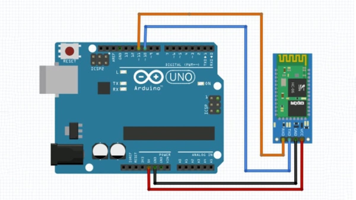
For the projects discussed here, I will use an HC-06 that is very popular and cheap (Bye, bye, Iphone! Androids are kings here!). The BT module is powered with 5V which makes it to be easily connected to an Arduino UNO for example. His transmit (Tx) and receive (Rx) pins can be connected directly to the UNO, with no need of voltage dividers as we see in the case of ESP8266. Usually the HC-06 should be connected directly to pins 0 and 1 Arduino (“Serial 0”):
- HC06-Tx to Arduino pin 0 (Rx)
- HC06-Rx to Arduino pin 1 (Tx)
When using “Serial 0” inputs (the only HW Serial port at UNO), it is very important to remember that the HC-06 may not be physically connected to pins 0 and 1 during the program load, because the USB port also use the same serial. A simple way to get around this little problem (if your project does not use many GPIOs UNO) is to use a “SW serial port” through the library SoftwareSerial. In our case here, we will use the pins 10 and 11 of UNO (Tx, Rx respectively).
Step 2: Testing and Configuring the HC-06
The next step will be to write a simple code in order to test, program and initialize the HC-O6:
To start, include the Library Software Serial, setting the “BT” variable to the new serial port.
#include <SoftwareSerial.h>
SoftwareSerial BT (10, 11); // RX, TX

String command = ""; // Stores response of bluetooth device

void setup ()
{
  Serial.begin (9600);
  Serial.println ("Type AT commands");
  BT.begin (9600); // HC-06 Usually default baud-rate
}
Then comes the main body of code that simply waits for data coming from the BT. When arrived, data are written in the Serial Monitor. Likewise, AT commands can be sent from the serial monitor to the HC-06 module.
void loop ()
{
  if (BT.available ()) // receive data if available.
  {
    while (BT.available ()) // "keep receiving".
    {
      delay (10); // Delay added to make thing stable
      char c = BT.read (); // Conduct serial read
      command + = c; // Build the string.
    }
    Serial.println (command);
    command = ""; // No repeats
  }
  if (Serial.available ())
  {
    delay (10);
    BT.write (Serial.read ());
  }
}
Once the program is loaded, using the Serial monitor do some basic tests, for example:
- Send ” AT “, the module should respond ” OK “.
- Ask firmware version: ” AT + VERSION”, the module must responser, for example: ” linvorV1.8 “.
- With HC-06 you can define a name for the module for example: “The T + NAMEMJRoBot_BT_HC06 “. But unlike other modules, you can not know what is the name that is set for the module. When sending the previous command, the HC-06 simply answer: “OKsetname” .
In general, the HC-O6 comes standard with the password (or PIN): 1234. You can set a new one with the AT command:
- AT + PIN xxxx where ‘ xxxx ‘ will be 4 numbers.
Bellow the Arduino code for HC-06 test:
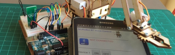
Step 3: The Android Device
OK! Module connected to UNO and running. It is time to introduce the Android device.
There are many apps on the Google store that can be used. I will use an app that was developed by me using the MIT Application2 tool and available free of charge at the Google store:
MJRoBot BT Digital Analog Voice Control
The App sends digital commands (thru buttons or voice) and analog commands to control PWMs devices like servos (send data ranged 0 to 255).
- Download the App,
- Go to the Android device set-up and look for the BT module and make the connection (enter PIN 1234 or any other defined by you). This should be done once, as the device will keep the connection data.
- Once the device and the HC-06 are talking, launch the App. On a second time, when launching the app, the BT module should be connected automatically.
- Select the module name (in my case is the one with the HC-06 at the end).
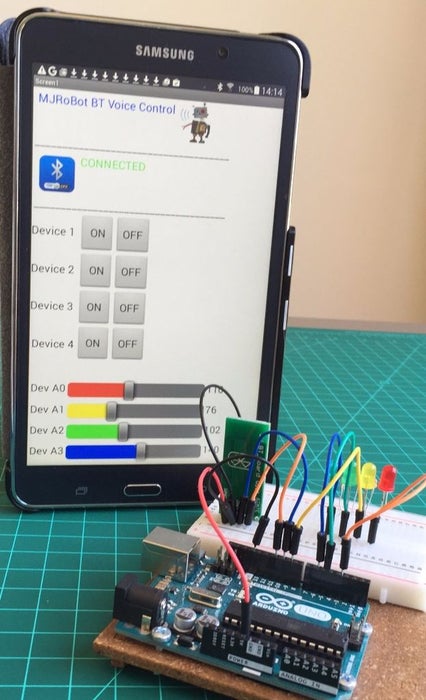
The App will then show “CONNECTED”, informing that it is “pared” with the HC-06
At this point, test the App buttons and watch at your PC Serial Monitor, what data the App is sending.
For example, pressing the buttons “ON” and “OFF” sequentially for the 4 Devices, the result would be:
dev1on
dev1off
dev2on
dev2off
dev3on
dev3off
dev4on
dev4off
Now that we have an App for Android talking with the BT module, let’s create something useful!.
Step 4: Controlling Arduino Outputs.
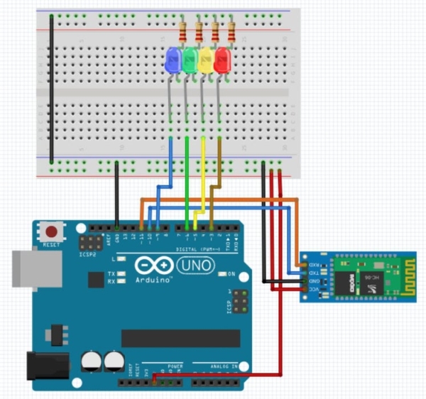
Let’s build the circuit as shown above.
The idea is to use the App to turn ON and OFF the LEDS and also controlling their intensity.
Connections:
- Device 1: “dev1on / dev1off” ==> LED Red ==> Pin 3 UNO
- Device 2: “dev2on / dev2off” ==> LED Yellow ==> Pin 5 of the UNO
- Device 3: “dev3on / dev3off” ==> LED Green ==> Pin 6 UNO
- Device 4: “dev4on / dev4off” ==> LED Blue ==> Pin 9 of the UNO
That is, to trigger the “ON” related to “Device 1” button, the text message “dev1on” will be sent to the Arduino. Upon receiving this message, the red LED should light and so on.
Note that the 4 pins are the pins capable of generating PWM (not all UNO digital pins can die it. look for the ones market with “~”. This is important for the use of “sliders” at the App, to send numeric data to control the intensity of the LEDs through PWM:
- Dev A0: “r / 0-255” ==> LED Red ==> Pin 3 UNO
- Dev A1 “y / 0-255” ==> LED Yellow ==> Pin 5 of the UNO
- Dev A2: “g / 0-255” ==> LED Green ==> Pin 6 UNO
- Dev A3: “b / 0-255” ==> LED Blue ==> Pin 9do UNO
In the case of sliders, before the PWM data value (0 to 255), a character is sent to the Arduino to inform it that a ”slider” command is coming.
In the video bellow, a demonstration of the portion above program (Buttons & Slider):
Bellow the complete Arduino Code:
Read more: Connecting “stuff” Via Bluetooth / Android / Arduino