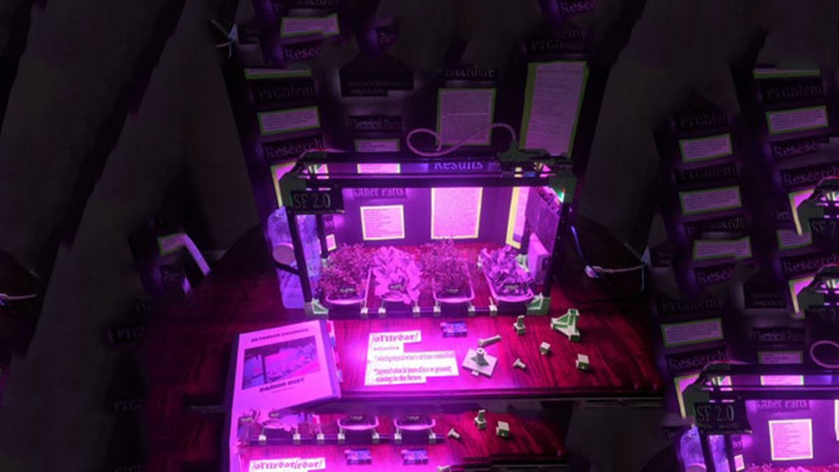
I designed a CNC Arduino Plant Watering machine for my local high school science and engineering fair. I ended up getting second place in the maths and engineering category, won $200 from the Missouri Society of Engineers, and was invited to compete in an international science fair in New York. With all that said this is not going to be a full Instructable of how to create this step by step. It is more of how I went about doing this along with tips to hopefully inspire others to want recreate my design and improve upon it.
Also I would really appreciate a vote for my project in the gardening contest! Thank you
Step 1: Gathering Parts
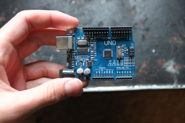
I started off this project by gathering my parts. This includes,
*10 Pack Black 2020 Aluminium Rods
*1kg Green PLA Filament
*1kg Black PLA Filament
*1X Endstop Switch
*12v LED Grow Light Stirp
*4X Linear Bearings
*12v Submersible Water Pump
*4X Arduino Soil Hygrometer
*6mm 20 Tooth Belt, Gear, and Pulley
*Arduino Uno
*3X 5v Single Channel Relay Module
*Nema 17 Stepper Motor
*Nema 17 Cable
*L298n Stepper Driver
*Water Reservoir
*PC Power Supply
*LOTS of Jumper Cables
*RTC Module
*Perf Board
*5ft of Acrylic Tubing
*4x Metal Bread Tins (Used to Hold Plants)
*Potting Soil
*Clear Spray Paint
*Wire Connector
*Multiple Screws and Bolts
I also used many 3D printed parts I designed along with other small random parts. In total the cost of this project was a little above $400.
Step 2: 3D Modeling and Printing
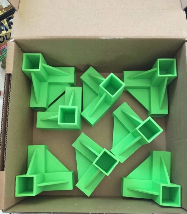
I modeled all parts for this project in Tinkercad, yes I know its Tinkercad but it works great for my needs and I love that it is web based so I can work on projects wherever there is a computer. I ended up printing 44 parts in total for this project. They were all printed in green and black PLA on my Prusa i3 Mk3. These parts include
*2020 Aluminium Corner Frame Connectors
*Linear Rod Holders
*Watering Head
*Linear Bearing Mounts
*Nema Mount
*Endstop Triggering Arm
*Hygrometer Holders
*Electronics Mounting Board & Cover
*Relay Mounts
*Sign
*Plant Labels
I also uploaded msot of the 3d models I made to Thingiverse, here is the link.
https://www.thingiverse.com/thing:3561109
Step 3: Assemling Frame & Mechanical Parts
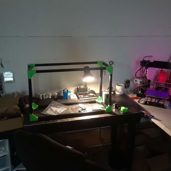
Once I had all the components I needed gathered, I started to work on the assembly of the whole thing. I started by laying out the aluminium extrusion and watering tank to get an idea of how big I would need to make this. Once I got an idea of how I wanted it to look I started cutting and screwing together the frame. I moved on to installing the grow LED’s.
I first was going to use some kind of bar in the middle of the top frame to hold one strand of the grow lights, but realized that the strips fit perfectly into the slots of the 2020. This also helped out by allowing me to install the lights in both the front and back 2020 so that way the plants could receive more even light. I then moved on to the watering head system.
This consisted of two linear steel rods held to the 2020 by some 3D printed brackets I designed, and had a set of linear bearings on each rod. The watering head base was screwed into the top of each bearing and after that the final watering head was attached. Next the water reservoir and pump were installed along with the hygrometers and pots.
Step 4: Wiring in the Electronics
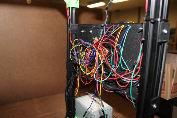
For the last step of the physical part of the build I installed all the electrical components and wired them together. For this part I watched a lot of videos and looked through many Instructables to learn how each component would need to be wired so they could work together. I used the Arduino Uno as the brains of the operation and added an RTC module to help keep the time. The RTC was used to turn the grow lights on at six in the morning, and turn them off at eight in the evening.
The Arduino used four hygrometers to read the moisture content of the four plants that it was taking care of. The hygrometers send a voltage through the soil and based on the amount of water in the soil it can read the resistance of the electricity sent through the two probes. If there is a high resistance the soil is dry, if there is a low resistance the soil is wet.
The three relays are used to turn on/off the grow lights, on/off the pump, and on/off the L298n. I had to use a relay to turn the power off to the L298n because the Nema 17 was always drawing current even when it wasnt in use so it could hold is torque. Because of that though the motor would overheat drastically since the machine is always running. I realized that just cutting the power off to the L298n is probably not the best way to fix the problem but it’s what I went with since I don’t know too much about steppers.
The last of the electrical components were used with the linear axis. I used the nema 17 to move the watering head using a 6mm belt, an endstop switch to home the watering head, and the L298n to control the nema. I based the watering head of off an axis from a 3d printer since that is what I am used to. It has two linear rods with linear bearings, is driven by nema and L298n, and home itself using an endstop to “figure out” where it is when it is needed.
To power it all I am using a PC power supply since it has outputs of 12v and 5v. I did however run into a problem were I would get wacky readings from the hygrometer and the Arduino would stutter because it wasn’t getting enough power. I couldn’t figure out if I just wired it wrong or if the power supply couldn’t handle all the components but I just figured it wasn’t big enough. I had to end up plugging in the Arduino through a USB to give it extra power it needed. It was a bummer because I was hoping to have the whole thing powered from one cable but I was running out of time till the science fair so I have been going with it. I hope to find a better power supply that I can switch out so I don’t have to take up two plugs.
Step 5: Coding (The Really Hard Part)

This definitely was the hardest for me. I started by finding the codes needed for each part to make it work, then experimented with mixing the codes with each other to start building the final code. I had to do lots of research and read through many Arduino forums to fix all the problems I was running into. I am just going to put the code in so I don’t have to explain it all. There are probably many problems with it and it probably doesn’t look to great but I am still pretty new to coding so give me a little slack.
#include  //Stepper Motor Library
#include  //RTC Library

boolean Boolean_State = 0; //Set Initial Boolean Value

const int Lights = 7; //Grow Lights Pin
const int Motor = 5; //Relay for L298n power
const int Pump = 4; //Water Pump Pin
const int Home = 3; //Endstop Switch pin
const int stepsPerRevolution = 200;
const int OnHour = 6; //Turn ON Lights at 6:00 AM
const int OnMin = 0;
const int OffHour = 20; //Turn OFF Lights at 8:00 PM
const int OffMin = 0;
#define turn;

DS3231  rtc(SDA, SCL); //RTC Input pins
Time t;

Stepper myStepper(stepsPerRevolution, 8, 9, 10, 11);

int buttonState = 0;
int p1 = A0; //Plant One Hygrometer
int p2 = A1; //Plant Two Hygrometer
int p3 = A2; //Plant Three Hygrometer
int p4 = A3; //Plant Four Hygrometer
int stepCount = 0;

void setup() {
  digitalWrite(p1, HIGH);
  digitalWrite(p2, HIGH);
  digitalWrite(p3, HIGH);
  digitalWrite(p4, HIGH);

  pinMode(Home, INPUT_PULLUP); //Use Internal Resistor
  pinMode(Motor, OUTPUT); //Motor Relay Output mode
  pinMode(Lights, OUTPUT); //Lights Relay OUTPUT Mode
  pinMode(Pump, OUTPUT); //Pump Relay OutPut Mode
  myStepper.setSpeed(60); //Stepper Motor Speed
  Serial.begin (115200);
  rtc.begin();
  digitalWrite(Lights, LOW); //Turn Lights ON
  digitalWrite(Pump, LOW); //Make sure Pump is OFF
  digitalWrite(Motor, HIGH); // Make sure motor is OFF
  }  void loop() {
  plants(); //Start Plant Loop
 Other(); //Start Other Loop
 }

void Other(){

 t = rtc.getTime();
 Serial.print(t.hour);
Serial.print(" hour(s), ");
Serial.print(t.min);
Serial.print(" minute(s)");
Serial.println(" ");

 if(t.hour == OnHour && t.min == OnMin){ //AT 6:00 AM Turn ON Lights
  digitalWrite(Lights, LOW);
  Serial.println("LIGHTS ON");
  }

if(t.hour == OffHour && t.min == OffMin){ //AT 10:00 PM Turn OFF Lights
  digitalWrite(Lights, HIGH);
  Serial.println("LIGHTS OFF");
  }
  }
void plants(){

  if(Boolean_State == 1) { //If Boolean is Changed
  digitalWrite(Motor, HIGH);//Turn off Motor Relay
  Boolean_State = !Boolean_State; //change Boolean Value
  }


int plant1 = analogRead(p1); //Read P1 Hygrometer Values
int plant2 = analogRead(p2); //Read P2 Hygrometer Values
int plant3 = analogRead(p3); //Read P3 Hygrometer Values
int plant4 = analogRead(p4); //Read P4 Hygrometer Values
buttonState = digitalRead(Home);     //PLANT ONE
if (plant1 >= 700){ //If Plant One Needs Watered
if (Boolean_State == 0 ){
  digitalWrite(Motor, LOW); //Turn ON Motor Relay
  Boolean_State = !Boolean_State; //Change Boolean Value
  }
if (buttonState == HIGH); //If Endstop is Not Switched
{
  myStepper.step(-5); //Home Watering Head
}
if (buttonState == LOW) //When Endstop Hit
{
myStepper.step(50); // GoTo Plant One
digitalWrite(Pump, HIGH); //Pump On
delay(2000);
digitalWrite(Pump, LOW); //Pump Off
delay(10000);
digitalWrite(Motor, HIGH);
Boolean_State = !Boolean_State;
}
}

//PLANT TWO
if (plant2 >= 700){ //If Plant One Needs Watered

if (Boolean_State == 0 ){
  digitalWrite(Motor, LOW); //Turn ON Motor Relay
Boolean_State = !Boolean_State; //Change Boolean Value
}
if (buttonState == HIGH); //If Endstop is Not Switched
{
  myStepper.step(-5); //Home Watering Head
}

if (buttonState == LOW) //When Endstop Hit
{
myStepper.step(900); // GoTo Plant One
digitalWrite(Pump, HIGH); //Pump On
delay(2000);
digitalWrite(Pump, LOW); //Pump Off
delay(10000);
digitalWrite(Motor, HIGH);
Boolean_State = !Boolean_State;
}
}

//PLANT THREE
if (plant3 >= 700){ //If Plant One Needs Watered

if (Boolean_State == 0 ){
  digitalWrite(Motor, LOW); //Turn ON Motor Relay
Boolean_State = !Boolean_State; //Change Boolean Value
}
if (buttonState == HIGH); //If Endstop is Not Switched
{
  myStepper.step(-5); //Home Watering Head
}
if (buttonState == LOW) //When Endstop Hit
{
myStepper.step(1750); // GoTo Plant One
digitalWrite(Pump, HIGH); //Pump On
delay(2000);
digitalWrite(Pump, LOW); //Pump Off
delay(10000);
digitalWrite(Motor, HIGH);
Boolean_State = !Boolean_State;
}
}

//PLANT FOUR
if (plant4 >= 700){//If Plant One Needs Watered

if (Boolean_State == 0 ){
digitalWrite(Motor, LOW); //Turn ON Motor Relay
Boolean_State = !Boolean_State; //Change Boolean Value
}
if (buttonState == HIGH); //If Endstop is Not Switched
{   myStepper.step(-5);
}//Home Watering Head }
if (buttonState == LOW) //When Endstop Hit
{
myStepper.step(2550); // GoTo Plant One
digitalWrite(Pump, HIGH); //Pump On
delay(2000);
digitalWrite(Pump, LOW); //Pump Off
delay(10000);
digitalWrite(Motor, HIGH);
  Boolean_State = !Boolean_State;

} }
}
Source: CNC Arduino Plant Growing Machine
