Summary of Arduino powered camera slider and pan-tilt camera mount
This article details an open-source, Arduino-powered motorized camera slider and pan-tilt mount designed by YouTuber "isaac879" for DSLR video motion control and time-lapses. The system combines 3D printed parts with aluminum extrusion and utilizes a custom PCB featuring Bluetooth, auto-homing via Hall effect sensors, and camera shutter triggering capabilities. It supports precise movements down to 0.0125mm and is powered by either 12V DC or a LiPo battery.
Parts used in the Arduino powered camera slider and pan-tilt camera mount:
- DSLR Canon EOS 250D
- 3D printed parts
- M3 nuts and bolts
- 2020 V-slot aluminium extrusion
- CPCB (Custom Printed Circuit Board)
- Stepper driver
- Hall effect sensor
- Arduino Nano
- RGB status LED
- 2GT timing belt
- 20 tooth timing pulley
- NPN transistor
- 2.5mm 3 pole jack
- 12V DC input
- 3 cell LiPo battery
Photographers searching for a professional style motorised camera slider and pan-tilt camera mount, may be interested in a new project by YouTuber “isaac879”. The project is open source with links to the design files and code provided via Github. Check out the first and second videos in the series below. “This is the pan tilt camera mount I designed for my DSLR Canon EOS 250D. I designed it for video motion control, time-lapses and panoramic shots.”
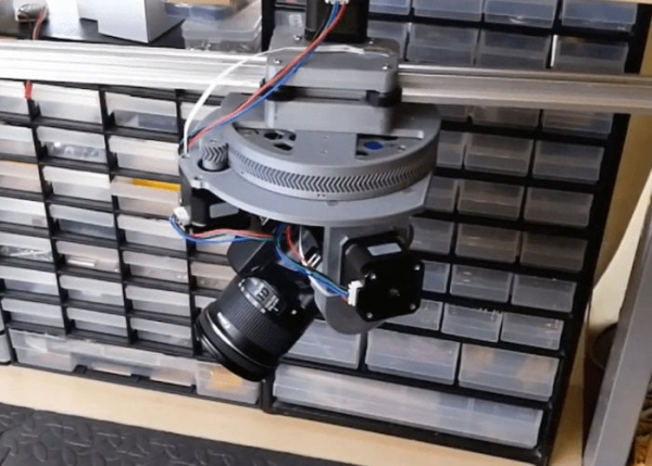
This is a continuation of the pan tilt mount project I designed for my DSLR Canon EOS 250D. Here I have designed and added a slider to the pan tilt mount which allows for more complex camera movements. The slider is made from mostly 3d printed parts, M3 nuts and bolts and 2020 V-slot aluminium extrusion. It uses the same PCB I created for my pan tilt mount which is why I included an extra stepper driver and breakout for another Hall effect sensor. As the same PCB is used it has all the features of the pan tilt mount, such as Bluetooth communication to the Arduino Nano, the RGB status LED, auto homing and the ability to trigger the cameras shutter.”
“The 2GT timing belt, 20 tooth timing pulley and 16th microstepping allow the slider to move with a precision of 0.0125mm. The movement speed can be set extremely slow for time-lapses or up to about 200mm/s (in full step mode). There are Hall effect sensors embedded in the pan and tilt axis to allow the stepper motors to home and zero themselves when powered on. The circuit can be powered by a 12V DC input or 3 cell LiPo battery for portability. The Arduino monitors the battery level and indicates its charge on the RGB status LED. The Arduino can also trigger the camera’s shutter using an NPN transistor and 2.5mm 3 pole jack.”
For more information and to download the files and code for the project jump over to the official GitHub page.
Source: Arduino powered camera slider and pan-tilt camera mount
- What is the primary purpose of this project?
The project is designed for video motion control, time-lapses, and panoramic shots using a DSLR. - How precise is the movement of the slider?
The 2GT timing belt and 20 tooth timing pulley with 16th microstepping allow for a precision of 0.0125mm. - Can the device be powered by a battery?
Yes, the circuit can be powered by a 3 cell LiPo battery for portability. - How does the system determine its home position?
Hall effect sensors are embedded in the pan and tilt axis to allow stepper motors to home and zero themselves when powered on. - Does the system support Bluetooth connectivity?
Yes, the PCB features Bluetooth communication to the Arduino Nano. - What is the maximum movement speed of the slider?
The movement speed can reach up to about 200mm/s in full step mode. - How does the Arduino indicate the battery charge level?
The Arduino monitors the battery level and indicates its charge on the RGB status LED. - How is the camera shutter triggered?
The Arduino triggers the camera's shutter using an NPN transistor and a 2.5mm 3 pole jack. - Where can I find the design files and code?
The files and code are available on the official GitHub page linked in the article.