The accuracy of any circuit or system that uses a thermocouple to determine the temperature of a process is limited by the accuracy of the method used to perform cold-junction compensation. In a thermocouple measurement, two wires of dissimilar metal join together at the “hot,” or measurement, junction.
The isothermal termination of the thermocouple wires provides a second “cold,” or reference, junction. The potential across the thermocouple is proportional to the temperature difference between the two junctions. Thus, to determine the absolute temperature of the hot junction, you must also know the absolute temperature of the cold junction. Tables of thermocouple voltage versus temperature use the assumption that the cold junction is maintained at 0°C. A somewhat impractical way to use these tables is to place the cold junction into an ice bath. A more practical way is to measure the temperature of the cold junction and then add an equivalent voltage to the one developed by the hot junction. You then find the temperature of the hot junction in the thermocouple tables.
A key issue to address is how to thermally bond the RTDs (resistance-temperature detectors) to the terminal block, which is the cold junction. If the temperature along the terminal block is constant, you could use a single sensor, thermally bonded to the block. If a linear temperature gradient exists along the terminal block, you could use a sensor at both ends of the block. This method allows for interpolation of the temperature at various points along the block. If the temperature gradient is nonlinear, you can add an electrically isolated copper strip along the length of the block to minimize the nonlinearity. In the extreme case, you could use a temperature sensor per thermocouple pair with each sensor, thermally bonded to its respective junction.
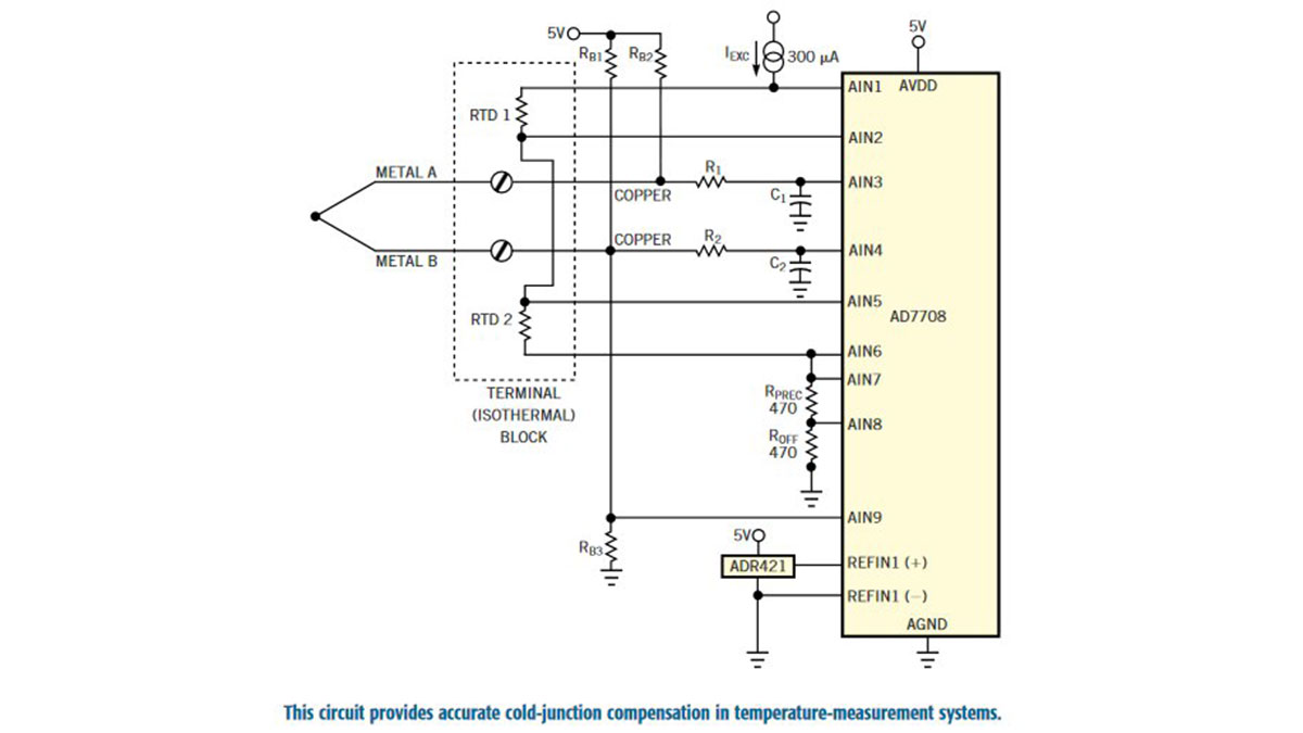
The design in Figure 1 uses a multichannel, high-resolution ADC to measure the thermocouple voltage and the resistance of two RTDs at the cold junction. Using the data from the ADC, a microprocessor determines the temperature of the cold junction, the amount of cold-junction compensation to apply, and, then, the temperature of the hot junction. Performing the cold-junction compensation in software allows users to use mixed thermocouple types and is both flexible and universal. The AD7708 digitizes the signals from the thermocouple and from two three-wire RTD sensors, which measure the cold-junction temperature at both ends of the terminal block. The terminal block is local, so you can ignore the wiring resistance between the ADC and the RTDs. It is easier to obtain precision resistors and voltage references than precision current sources, so the RTDs and the 470Ω precision resistor, RPREC, connect in series, and all obtain excitation from the same current source, IEXC. The voltage generated across RPREC determines the exact value of the excitation current. Hence, the current source need not be particularly stable over temperature. ROFF offsets input pair AIN7/-AIN8 by more than 100 mV from ground. ROFF is also a 470Ω resistor but need not be a precision resistor. The ADR421’s 2.5V precision voltage reference directly drives the REFIN1(+)/REF-IN1(–) inputs.
Read more: Circuit provides cold-junction compensation